Eureka AIR delivers breakthrough ideas for toughest innovation challenges, trusted by R&D personnel around the world.

Automatic pipeline damping manufacturing device and automatic pipeline damping manufacturing method

A technology for making devices and pipes, used in manufacturing tools, metal processing, metal processing equipment, etc., can solve the problems of difficulty in mass production, time-consuming and laborious, and it is difficult to ensure consistency and interchangeability, so as to ensure accuracy and consistency. The effect of high performance and convenience

Pending Publication Date: 2020-02-28
ZHEJIANG COLLEGE OF CONSTR
View PDF0 Cites 0 Cited by
  • Summary
  • Abstract
  • Description
  • Claims
  • Application Information

AI Technical Summary

Problems solved by technology

However, manual knocking has great defects. It is difficult to ensure consistency and interchangeability, and it is difficult to produce in batches. The parameters of each instrument need to be fine-tuned, or the damping test must be repeated, which is time-consuming and laborious.

Method used


Image

  • Automatic pipeline damping manufacturing device and automatic pipeline damping manufacturing method
  • Automatic pipeline damping manufacturing device and automatic pipeline damping manufacturing method
  • Automatic pipeline damping manufacturing device and automatic pipeline damping manufacturing method

Examples


Embodiment 1

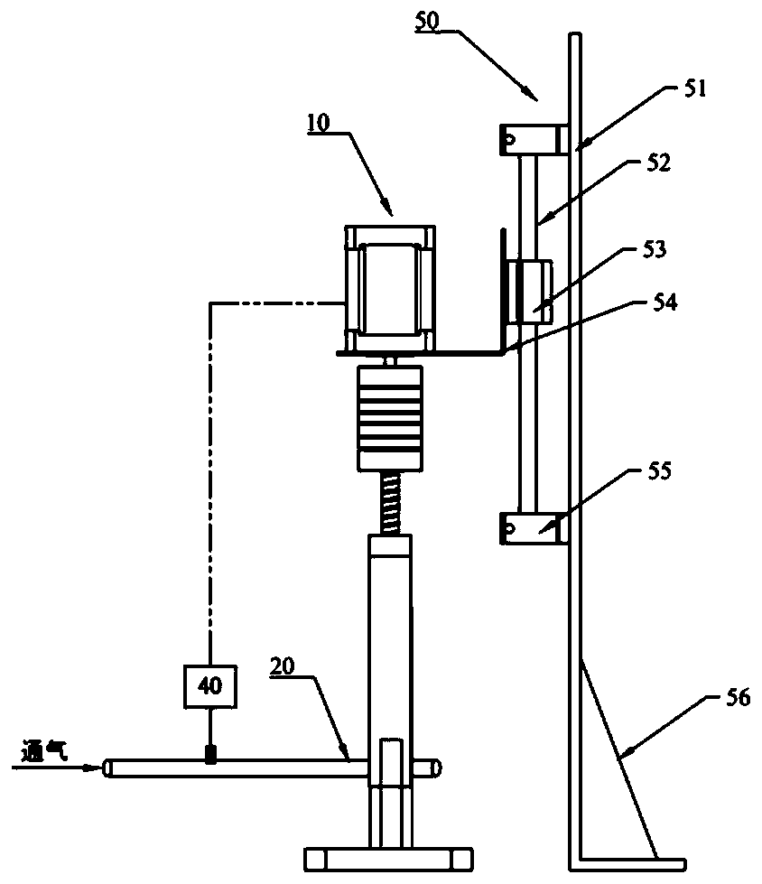
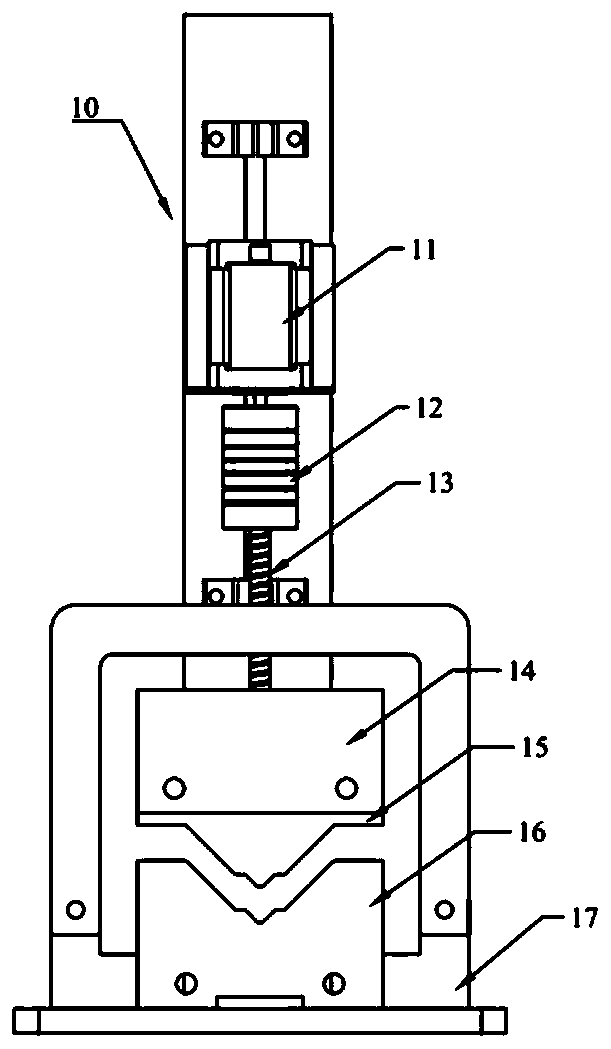
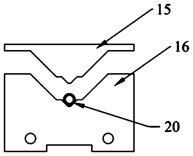
[0034] Such as Figure 1-4 As shown, the pipeline damping automatic manufacturing device provided in this embodiment includes a driving mechanism 10, an upper pressing block 15, a lower pressing block 16 and a gas flow meter 40, the lower pressing block 16 is provided with a pipeline processing groove, and the upper pressing block 15 is provided with a pressing Protrusion; gas flowmeter 40 is arranged on pipeline 30 to be made damping, and one side of pipeline 30 is ventilated; Gas flowmeter 40 is electrically connected to driving mechanism 10, and pipeline 30 stretches in the pipeline processing groove of lower pressing block, and is positioned at At a damping point, the driving mechanism 10 drives the upper pressing block 15 to move downward, and the pressing protrusion of the lower pressing block 16 presses the pipeline downward until the gas flow meter 40 reaches the required flow value, and the driving mechanism 10 stops.

[0035] The drive mechanism 10 used in this embod...

Embodiment 2

[0041] This embodiment also provides a method for automatically producing pipeline damping, using the automatic pipeline damping production device described in Embodiment 1, including at least the following steps:

[0042] S1, connect the pipeline to be damped to the gas measuring instrument, and ventilate on one side of the pipeline;

[0043]S2, extending the pipeline to be damped into the pipeline processing groove of the lower pressing block, and positioning it to a damping production point;

[0044] S3, the driving mechanism drives the upper pressing block to move downward, and the pressing protrusion of the upper pressing block presses the pipeline downward until the gas flowmeter reaches the required flow rate, the driving mechanism stops;

[0045] S4, setting a limiting block in the limiting groove between the upper pressing block and the lower pressing block;

[0046] S5, moving the pipeline to put another damping point into the pipeline processing groove of the lower...


PUM


Abstract

The invention discloses an automatic pipeline damping manufacturing device and an automatic pipeline damping manufacturing method. The automatic pipeline damping manufacturing device comprises a driving mechanism, an upper pressing block, a lower pressing block and a gas flowmeter. The lower pressing block is provided with a pipeline machining groove, and the upper pressing block is provided witha pressing protrusion. The gas flowmeter is arranged in a pipeline for which damping is about to be manufactured, and one side of the pipeline is ventilated; and the pipeline extends into the pipelinemachining groove of the lower pressing block and is positioned to a damping manufacturing point, the driving mechanism drives the upper pressing block to move downwards, the pressing protrusion of the lower pressing block presses the pipeline downwards until the gas flowmeter reaches the required flow value, and the driving mechanism stops working. According to the automatic pipeline damping manufacturing device and the automatic pipeline damping manufacturing method, mass damping manufacturing can be realized, the consistency and interchangeability of the damping are ensured, the workload isreduced, the working time is shortened, and the efficiency is improved.

Description

technical field [0001] The invention relates to the field of pipeline damping production, and is suitable for pipeline damping production in various chromatographic detection instruments, in particular to an automatic pipeline damping production device and a production method thereof. Background technique [0002] The pipelines used inside the chromatographic detection instrument need to increase the damping to control the flow and velocity. At present, the method used by people is to knock the pipeline by hand to deform it to increase the damping of the pipeline and realize the control of flow and velocity. However, manual knocking has great defects. It is difficult to ensure consistency and interchangeability, and it is difficult to produce in batches. The parameters of each instrument need to be fine-tuned, or the damping test must be repeated, which is time-consuming and laborious. Contents of the invention [0003] In order to solve the problems existing in the above-...

Claims


Application Information

Patent Timeline
Patent Type & Authority Applications(China)
IPC IPC(8): B21D15/04B21C51/00
CPCB21C51/00B21D15/04
Inventor 贾淑红王晓宇
Owner ZHEJIANG COLLEGE OF CONSTR
Why Eureka
Eureka Blog
Learn More