
Electric double-head counter-rolling toothbrush head structure

A double-headed, electric technology, used in dentistry, cleaning teeth, medical science and other directions, can solve the problems of easy collision with teeth, damage to the inner wall of the oral cavity, and affect the comfort of brushing, so as to improve the comfort of use, improve the comfort of brushing, Reduces the effect of constant friction against the walls of the mouth

Pending Publication Date: 2020-02-28
王众城
View PDF1 Cites 3 Cited by
  • Summary
  • Abstract
  • Description
  • Claims
  • Application Information

AI Technical Summary

Problems solved by technology

[0003] However, there are still the following problems in the scheme disclosed in the above-mentioned patent documents: 1. When brushing teeth, the two brush head bodies rotate, and the back of the brush head body will contact and rub against the oral cavity wall during the movement, which affects the comfort of brushing teeth Spend
On the back of the two brush head bodies, the interlaced parts are directly exposed, and there is a potential risk of damage to the inner wall of the oral cavity
In addition, during the brushing process, the back of the high-speed vibrating brush head may easily collide with the teeth, causing discomfort
2. In the brush heads disclosed in the above documents, the shaft connected to the brush body not only serves as a transmission shaft, but also serves as the rotation axis of the brush body. Since the shaft connected to the brush body requires Extending down to the handle, the length of the shaft is longer, and after the brush head body is connected to the shaft, most of the weight of the brush head body is located outside the shaft, such a design will easily cause the brush head body to rotate There is beating / vibration in the middle, so that the two brush head bodies rub against the contact part to generate noise
3. Since the rotation axis of the brush head body (that is, the aforementioned shaft) is located in the middle or on the inner side of the width direction (the so-called "inside" refers to the side where the tooth-shaped gap is opened on the brush head body, the so-called "outside" Refers to the position on the side opposite to the inner position. When the brush head body rotates, the movement range of the outer side is relatively large, and the outer side of the brush head body is also the part that will be in contact with the oral cavity wall. The outer wall of the brush head body is relatively large Friction against the oral wall, further affecting the comfort of brushing teeth

Method used


Image

  • Electric double-head counter-rolling toothbrush head structure
  • Electric double-head counter-rolling toothbrush head structure
  • Electric double-head counter-rolling toothbrush head structure

Examples


Embodiment 1

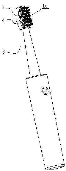
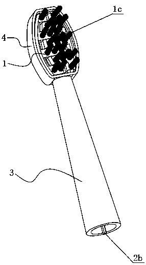
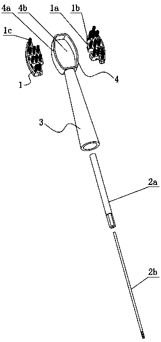
[0040] See Figure 1-3 As shown, in the brush head structure of the electric double-ended rolling toothbrush involved in this embodiment, the aforementioned transmission component includes a hollow shaft 2a and a central shaft 2b, the hollow shaft 2a and the central shaft 2b are coaxially arranged, and the hollow shaft 2a The top of the brush head is connected to a brush head body 1, the central shaft 2b is penetrated in the hollow shaft 2a and its top end protrudes from the top of the hollow shaft 2a and is connected to another brush head body 1. By driving the hollow shaft 2a and the central shaft 2b reciprocating rotation in opposite directions can drive the two brush head bodies 1 to perform reciprocating rolling motion. It should be noted that the present invention does not involve an improvement in how to drive the hollow shaft 2a and the central shaft 2b to reciprocate in opposite directions. The means for the direction reciprocating rotation will not be repeated here....

Embodiment 2

[0044] Unlike Examples 3-4, see Figure 4-6 As shown, in this embodiment, the transmission component includes a transmission shaft 2c, which penetrates into the inner cavity of the brush neck 3, the top end of the transmission shaft 2c is provided with a guide groove 2c1, and the bottom end of each brush head body 1 is provided with a guide groove 2c1. Each is connected with a transmission rod 2d, and the guide grooves 2c1 are connected end to end in a closed shape and are eccentrically arranged relative to the transmission shaft 2c (it can be understood that the axis of the transmission shaft 2c is located in the area surrounded by the guide groove 2c1, but the guide groove 2c1 The center is not in the same position as the axis of the transmission shaft 2c), the transmission rod 2d is inserted into the guide groove 2c1 downward, when the transmission shaft 2c rotates, the side wall of the guide groove 2c1 pushes against the transmission rod 2d and drives the transmission rod 2...

Embodiment 3

[0048] The difference between this embodiment and Embodiment 2 is mainly that the structure of the transmission mechanism driving the brush head body 1 to rotate is different. For details, see Figure 7-9 shown (the aforementioned bristles 1c are Figure 7-9 (not shown in the figure), the transmission component includes a crankshaft 2e, the crankshaft 2e is penetrated into the inner cavity of the brush neck 3, the bottom end of the brush head body 1 is connected with a connecting rod 2f, and the connecting rod 2f is provided with a strip hole 2f1, The top end of the crankshaft 2e passes through the bar-shaped hole 2f1 of one connecting rod 2f and is inserted into the bar-shaped hole 2f1 of the other connecting rod 2f. When the crankshaft 2e rotates, the outer peripheral surface of the crankshaft 2e pushes against the side wall of the bar-shaped hole 2f1 And drive the connecting rod 2f to swing reciprocatingly with the corresponding connecting shaft 5 as the center, and then d...


PUM


Abstract

An electric double-head counter-rolling toothbrush head structure comprises two brush head bodies, a transmission component, a hollow neck and a back shell. The transmission component is used for connecting the brush head bodies with the output end of a motor. The back shell comprises a side wall and a back wall. The side wall is arranged on the periphery of the back wall in an encircling mode, and is connected with the back wall. An accommodating cavity is formed in the back shell. The two brush head bodies are arranged in the accommodating cavity. The top end of the neck is fixedly connectedwith the back shell. A through hole communicated with an inner cavity of the neck is formed in the side wall of the back shell. The transmission component passes through the through hole downwards toenter the inner cavity of the neck. Compared with conventional double-head counter-rolling toothbrushes, the electric double-head counter-rolling toothbrush head structure has the advantages that discomfort caused by the fact that reverse sides of the brush head bodies rub oral cavity walls and impact on teeth can be avoided, vibration generated during rotation of the brush head bodies can be relieved, and frictional noise can be reduced; the brush head thickness can be basically equivalent to that of conventional manual toothbrushes, thinner brush heads can easily extend into oral depths, and the tooth brushing effect is better.

Description

technical field [0001] The invention relates to the technical field of personal cleaning appliances, in particular to a brush head structure of an electric double-head counter-rolling toothbrush. Background technique [0002] Chinese patent document CN109223231A discloses a variety of brush head structures for electric counter-rolling toothbrushes. These brush heads disclosed in the document are simplified in transmission structure compared with previous counter-rolling toothbrush heads, and the overall structure of the brush head has also become more compact. , which is conducive to the reduction of mass production costs. [0003] However, there are still the following problems in the scheme disclosed in the above-mentioned patent documents: 1. When brushing teeth, the two brush head bodies rotate, and the back of the brush head body will contact and rub against the oral cavity wall during the movement, which affects the comfort of brushing teeth Spend. Since the interlac...

Claims


Application Information

Patent Timeline
IPC IPC(8): A61C17/34
CPCA61C17/3418A61C17/349
Inventor 王众城王遥王翔
Owner 王众城
Learn More