
A Probe for Ultrasonic Testing of Air Duct Electron Beam Welds

An electron beam welding seam and air duct technology, which is applied to the analysis of solids using sound waves/ultrasonic waves/infrasonic waves, the use of sound waves/ultrasonic waves/infrasonic waves for material analysis, and measuring devices. problems, to achieve reliable detection results, significant economic benefits, and strong operability

Active Publication Date: 2021-12-10
SHENYANG LIMING AERO-ENGINE GROUP CORPORATION
View PDF0 Cites 0 Cited by
  • Summary
  • Abstract
  • Description
  • Claims
  • Application Information

AI Technical Summary

Problems solved by technology

Due to the high working temperature and the poor control of the electron beam welding process, defects such as cracks are prone to occur at the position of the weld seam, which directly affects the flight safety of the aircraft
According to the design requirements, the electron beam weld of the air duct needs to be ultrasonically inspected. The structure of the end weld is complex, the weld height is about 3mm, and it can only be incident from the inner hole. The diameter of the inner hole is only 116m, and the total height of the part exceeds 900mm. The existing probe It is not easy to couple on the surface of the boss weld seam; in addition, the chamfer of the oval hole outside the weld seam on the end face of the air duct and the chamfer of the inner hole affect the coverage of the ultrasonic sound beam
Ultrasonic testing cannot be realized without an ultrasonic probe suitable for testing

Method used


Image

  • A Probe for Ultrasonic Testing of Air Duct Electron Beam Welds
  • A Probe for Ultrasonic Testing of Air Duct Electron Beam Welds
  • A Probe for Ultrasonic Testing of Air Duct Electron Beam Welds

Examples


Embodiment Construction

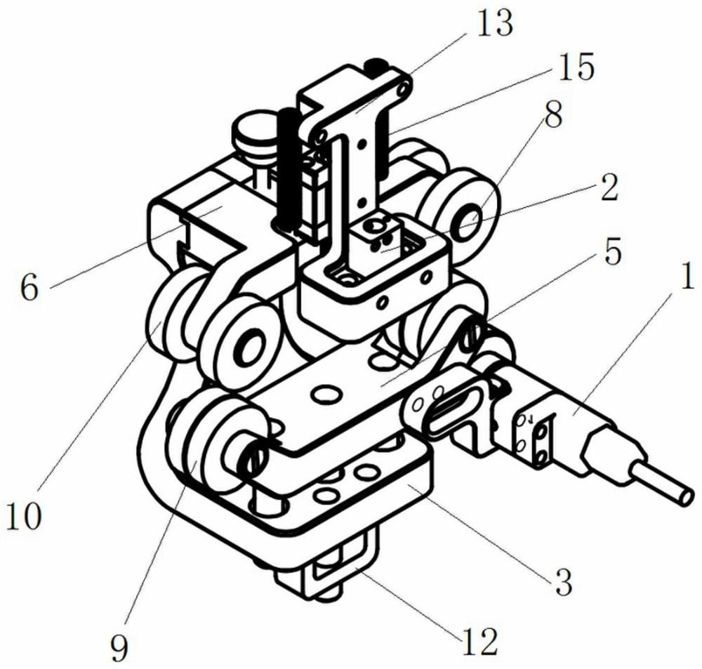
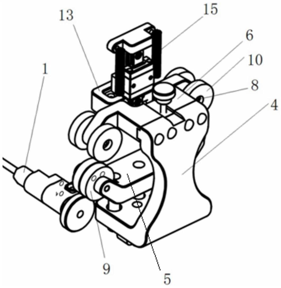
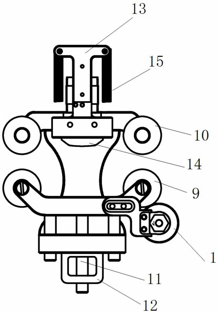
[0029] according to Figure 1-5 As shown, an air duct electron beam weld seam ultrasonic detection probe includes an encoder 1, a probe 2 and a tooling 3;

[0030] The encoder 1 and the probe 2 are fixed on the tooling 3;

[0031] The tooling includes a hand-held scanning frame 4, an upper bracket 5 and a lower bracket 6, and the hand-held scanning frame 4 is in the shape of an L frame;

[0032] The upper bracket 5 and the lower bracket 6 are in a figure-eight shape, the two ends of the upper bracket 5 are provided with notches 7 for installing rubber wheels, and the two ends of the lower frame 6 are provided with installation shafts 8, and there is an installation groove in the middle;

[0033] Both ends of the upper bracket 5 are provided with two lower rubber wheels 9 inside and outside, and the two lower rubber wheels 9 are closely placed, and the two lower rubber wheels 9 are inserted into the mounting holes of the upper bracket 5 through the shaft. The lower rubber whe...


PUM


Abstract

The invention discloses an air duct electron beam welding seam ultrasonic detection probe, which includes an encoder, a probe and tooling; The upper rubber wheel of the circle and the lower rubber wheel of the inner circle are designed at the chamfer of the air duct profile to play a limiting role; in the state of tooling limit, the phased array probe is aligned with the position of the inner hole of the weld being prepared, The wedge of the probe is designed with a convex surface, which makes the inner hole of the air duct easy to couple. The probe is fixed on the tooling, but it is equipped with a spring, which can ensure that the probe is well coupled and moves smoothly during the movement of the tooling. Phased array The probe can realize the deflection of the sound beam, which can avoid the obstruction of the sound beam by the chamfer of the incident surface and the oval hole at the end of the weld to the greatest extent, and the imaging area of ​​the phased array is large, and the detection image is intuitive and easy to judge; the encoder is designed on the outer circle, according to the rubber The movement of the wheel can record the root trajectory of the entire set of probes, and can reduce the interference between the encoder and its wires and the operator's hand.

Description

technical field [0001] The invention relates to the technical field of non-destructive testing ultrasonic testing, in particular to an ultrasonic testing probe for an electron beam welding seam of an air duct. Background technique [0002] The air duct is an important part of the turbine rotor assembly. Its front section and duct body are welded with electron beams. Its main function is to guide the air inside the engine, and the working temperature gradually rises from the front to the rear (intake direction of the engine). High, between about 300°C-450°C. Due to the high working temperature and the poor control of the electron beam welding process, defects such as cracks are prone to occur at the welding seam position, which directly affects the flight safety of the aircraft. According to the design requirements, the electron beam weld of the air duct needs to be ultrasonically inspected. The structure of the end weld is complex, the weld height is about 3mm, and it can o...

Claims


Application Information

Patent Timeline
Patent Type & Authority Patents(China)
IPC IPC(8): G01N29/04G01N29/24
CPCG01N29/04G01N29/24G01N2291/2675
Inventor 朱萍董德秀柏镇杜萍
Owner SHENYANG LIMING AERO-ENGINE GROUP CORPORATION
Learn More