High-voltage dry reed electric contact device

An electrical contact and reed technology, which is applied in the field of testing equipment, can solve the problem that the magnet and the reed switch have a large attraction and disconnection force, the large magnetic magnet is short board, and the pressure gauge movement cannot drive the movable conductive needle to open and close, etc. question

Inactive Publication Date: 2020-02-25
JINAN JINBAOMA ELECTRONICS INSTR CO LTD
View PDF9 Cites 0 Cited by
  • Summary
  • Abstract
  • Description
  • Claims
  • Application Information

AI Technical Summary

Problems solved by technology

[0002] The reed electrical contact is mainly used in pressure gauges as an alarm trigger mechanism for the pressure gauge to reach the set value. The existing reed electrical contact device cannot install a high-voltage reed switch larger than the ordinary reed switch in the structural space. This has just resulted in the limited application of existing dry reed contacts
In addition, the existing high-voltage reed switch needs a large magnetic force magnet control, which leads to the bottleneck factor of the magnetic force magnet control
If the current reed electrical contact uses a large magnetic force magnet, the large magnetic force will cause the magnet and the reed tube to attract and disconnect too much force, and the pressure gauge movement cannot drive the opening and closing of the movable conductive needle, resulting in the reed electrical contact. Short board using a large magnetic force magnet

Method used


Image

  • High-voltage dry reed electric contact device
  • High-voltage dry reed electric contact device

Examples


Embodiment 1

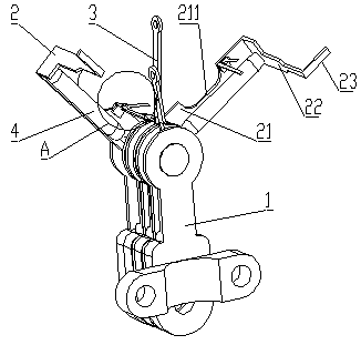
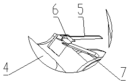
[0024] see figure 1 and figure 2 , the present invention provides a high-voltage dry reed electrical contact device, including a bracket 1, a shaft rod is arranged horizontally on the upper part of the bracket 1, and the shaft rod is rotated to connect two setting needles 2 and one end of the movable needle 3 for setting the upper and lower limits of the pressure gauge , the reed switch 4 is fixedly arranged on the setting pin 2, the setting pin 2 is a bent strip-shaped plate body, including the bottom plate 21 at the bottom, the bottom end of the bottom plate 21 is connected to the shaft in rotation, and the top of the bottom plate 21 is sequentially The middle plate 22 and the upper plate 23 are arranged, the plates of the middle plate 22 and the bottom plate 21 are vertical, the plates of the upper plate 23 and the bottom plate 21 are parallel, and the dry reed switch 4 is fixedly arranged on the plate of the bottom plate 21, and the dry reed The axis of the tube 4 is par...


PUM

PropertyMeasurementUnit
lengthaaaaaaaaaa

Abstract

The invention discloses a high-voltage dry reed electric contact device and relates to the field of detection equipment. The technical scheme is as follows, a shaft rod is horizontally arranged on a bracket, the shaft rod is rotatably connected with two setting needles and a movable needle for setting upper and lower limits of a pressure gauge, a reed switch is fixedly arranged on the setting needles, an elastic sheet is arranged on one side of the reed switch, one end of the elastic sheet is fixedly connected with the setting needles, the other end of the elastic sheet is a free end, a permanent magnet is fixedly arranged on one side of a lower portion of the elastic sheet facing the reed switch, and an included angle between a sheet body of the elastic sheet and the setting needles is anobtuse angle. The device has the advantage that the on-off control of a high-voltage reed switch is completed by employing a brand-new mode of operating the magnet. When the movable needle is far away, the elastic sheet can restore to an initial state due to the elasticity of the elastic sheet, in the process, the elastic sheet can drive the permanent magnet to be gradually far away from the reedswitch, and the reed switch is disconnected when a magnetic field is reduced to a certain value.

Description

technical field [0001] The invention relates to the field of detection equipment, in particular to a high-voltage reed electric contact device. Background technique [0002] The reed electrical contact is mainly used in pressure gauges as an alarm trigger mechanism for the pressure gauge to reach the set value. The existing reed electrical contact device cannot install a high-voltage reed switch larger than the ordinary reed switch in the structural space. This has limited the application of the existing reed electrical contacts. In addition, the existing high-voltage reed switch needs a large magnetic force magnet to control, which leads to the bottleneck factor of the magnetic force magnet control. If the current reed electrical contact uses a large magnetic force magnet, the large magnetic force will cause the magnet and the reed tube to attract and disconnect too much force, and the pressure gauge movement cannot drive the opening and closing of the movable conductive n...

Claims


Application Information

Patent Timeline
Patent Type & Authority Applications(China)
IPC IPC(8): G01L19/00G01L19/12
CPCG01L19/0061G01L19/12
Inventor 王浩阎乐囡
Owner JINAN JINBAOMA ELECTRONICS INSTR CO LTD
Why Eureka
Try Eureka