Hydraulic control valve

A technology of hydraulic control valves and spools, applied in fluid pressure actuators, servo motor components, oil supply tanks, etc., can solve problems such as maximum flow limitation, and achieve the effect of improving efficiency and power

Pending Publication Date: 2020-02-25
ROBERT BOSCH GMBH
View PDF4 Cites 0 Cited by
  • Summary
  • Abstract
  • Description
  • Claims
  • Application Information

AI Technical Summary

Problems solved by technology

As mentioned earlier, the maximum flow is limited by the spool travel

Method used


Image

  • Hydraulic control valve

Examples


Embodiment Construction

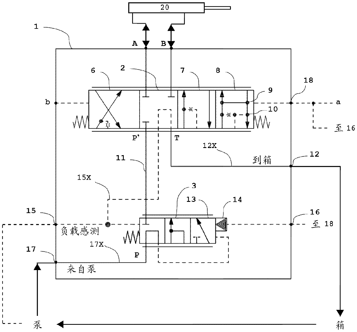
[0012] Before any embodiment of the invention is explained in detail, it is to be understood that the invention is not limited in its application to the details of construction and arrangement of components set forth in the following description or illustrated in the following drawings. The invention is capable of other embodiments and of being practiced or being carried out in various ways.

[0013] Referring now to the sole figure, a hydraulic control valve 1 is shown. The hydraulic control valve 1 is a closed central hydraulic control valve with pressure compensation. The valve 1 may be part of a hydraulic system suitable for use on the machine. The system with control valve 1 also includes a variable displacement pump of any suitable construction, such as disclosed in US Patent No. 4,695,230, issued September 22, 1987 to Lael B. Taplin, which is hereby incorporated by reference. Inside the control valve 1, among other suitable structures, known features of closed center ...


PUM


Abstract

The invention relates to a hydraulic control valve. A new means of achieving a valve float position in a closed centered hydraulic control valve. The valve has a main spool position whereby pressure compensator load sense control pressure is drained to tank through the main spool. Secondly, a pin acts on the pressure compensator to prevent the main pump flow from reaching the main section spool. Finally, the new spool position adds a connection from the consumer to tank, enabling a float position.

Description

technical field [0001] The invention relates to a closed center hydraulic control valve with pressure compensation for use with variable displacement pumps in working machines. Background technique [0002] Pressure compensation in closed center hydraulic control valves provides load independent flow control through the valve. One method of valve pressure compensation is to provide an in-line pressure compensator prior to the main spool. Valve pressure compensators provide a relatively constant pressure drop across the main spool. With a relatively constant pressure drop across the spool, flow is controlled by the area of ​​the spool opening, not by the pressure required by the consumer. Flow is then controlled by the area of ​​the spool opening such that larger openings result in greater flow and smaller openings result in less flow. [0003] Two features control the area of ​​the spool opening to the consumer. One characteristic is the size of the radial opening. The ...

Claims


Application Information

Patent Timeline
IPC IPC(8): F15B13/04
CPCF15B13/0417F15B13/0402F15B13/026F15B2013/0413F15B2211/30535F15B2211/3111F15B2211/3122F15B2211/50572F15B2211/575F15B2211/5756F15B13/0401F15B1/26
Inventor R.A.韦贝尔E.D.比亚洛斯基S.C.格雷厄姆F.C.卡斯滕D.S.拉西R.F.小塞勒
Owner ROBERT BOSCH GMBH
Why Eureka
Try Eureka