
A method for directional docking of cylindrical single crystals

A cylindrical, single crystal technology, applied in chemical instruments and methods, crystal growth, after treatment, etc., can solve problems such as cumbersome process, unstable axial crystal orientation, azimuth angle, and damage to sample integrity, so as to improve work efficiency , the effect of shortening the time

Active Publication Date: 2020-12-22
CHINA INSTITUTE OF ATOMIC ENERGY
View PDF10 Cites 2 Cited by
  • Summary
  • Abstract
  • Description
  • Claims
  • Application Information

AI Technical Summary

Problems solved by technology

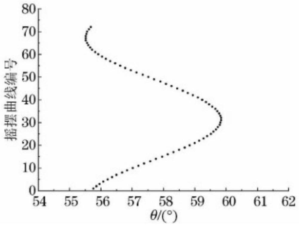
The disadvantage of this method is that the measurement time is too long, the efficiency is too low, and 72 reciprocal curves need to be measured
[0005] The common disadvantages of the above two methods are: (1) The deviation angle of each crystal orientation needs to be measured separately, which is time-consuming and laborious; (2) Judging whether the sample is single crystal or polycrystalline by the number of diffraction peaks may cause misjudgment
Disadvantages: (1) It needs to corrode and grind the sample, which destroys the integrity of the sample; (2) The process is cumbersome, and it needs to repeatedly use laser irradiation and X-ray diffraction; (3) The universality is not strong enough, different materials The single crystal needs to use different etching reagents and etching time
Defects: (1) The single crystal orientation process is cumbersome and requires many times of single crystal rotation before diffracting; (2) The determination of the best coincidence position of the Laue photo depends on the human eye, and human errors are large; (3) Selection of rods The axial direction of the crystal is used as the orientation reference, but the azimuth angle of the axial crystal direction is unstable, so it is not suitable to be used as the orientation reference

Method used


Image

  • A method for directional docking of cylindrical single crystals
  • A method for directional docking of cylindrical single crystals
  • A method for directional docking of cylindrical single crystals

Examples


Embodiment

[0076] The raw material used in the orientation experiment is a Mo alloy single crystal rod (Mo-3Nb) with a Nb content of 3% prepared by the electron beam suspension area melting furnace of the Northwest Nonferrous Metals Research Institute, with an outer diameter of 25 mm and an axial crystal orientation of . The complete process of single crystal directional docking is introduced in detail as follows:

[0077] 1) Excel pre-enters the calculation formulas of α and β angles, and [100][010][001] is preset in the single crystal diffractometer as the reference crystal orientation;

[0078] 2) Decontamination and polishing treatment on the surface of the single wafer rod;

[0079] 3) if Figure 8 As shown, fix the protractor on the single crystal A, place the sample and gently lean on the positioning probe, rotate the sample until the pointer of the protractor coincides with the 0 degree of the disc, fix the sample, and lift the sample stage to ensure that the X-rays ar...


PUM


Abstract

The invention relates to a cylindrical single crystal directional docking method. The method includes acquiring Laue photos of single crystal A and single crystal B samples through a single crystal diffractometer, and calibrating the Laue photos to obtain a transformation matrix of the crystallographic coordinate system and the sample appearance coordinate system of the two single crystals respectively; through the transformation matrixes, calculating the angle of deviation alpha and the azimuth angle beta of the crystal orientation of two single crystals in the same non-axial crystal orientation respectively, so as to obtain crystal orientation projection positions of the two single crystals in the side surfaces of the samples so that the crystal orientation projection positions overlap to achieve docking of the single crystal A and the single crystal B. The method is intuitive and efficient, the orientation process will not cause damage to the samples, and misjudgment of single crystal or polycrystal is not liable to occur.

Description

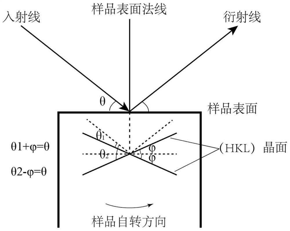
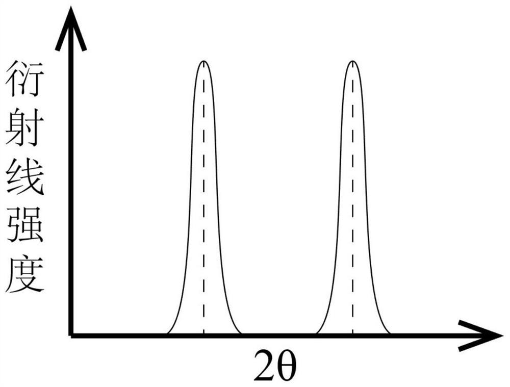
technical field [0001] The invention relates to single crystal orientation technology, in particular to a columnar single crystal orientation docking method. Background technique [0002] There are currently two methods for determining the orientation of a single crystal by X-ray polycrystal diffractometer. [0003] The first one is the X-ray θ scanning rotation method ([1] Guo Zhenqi, Li Fei, Zhu Shifu. Application of new device for XRD single crystal orientation[J]. Laboratory Science, 2011,14(6):92-96.[2 ] Liu Jingyan, Li Peng, Miao Zhuang. Comparison of two methods for measuring the off-angle of refractory single crystal planes[J]. The crystal system and lattice constant of the known material, such as figure 1 As shown, the diffraction angle θ of the target crystal plane (HKL) is calculated according to the Bragg diffraction law, and then the angle between the incident ray and the detector is fixed as (Π-2θ) and the incident ray, diffraction line and the normal of the ...

Claims


Application Information

Patent Timeline
Patent Type & Authority Patents(China)
IPC IPC(8): G01N23/22C30B33/06G06F30/20G06F30/12
CPCC30B33/06
Inventor 郑剑平赵建
Owner CHINA INSTITUTE OF ATOMIC ENERGY
Learn More