Battery mounting and carrying device for new energy automobile
A new energy vehicle, handling device technology, applied in electric vehicles, battery pack components, circuits, etc., can solve the problems of trouble, batteries and handling equipment are not integrated, battery volume and weight, etc., to achieve convenient battery installation. Effect
- Summary
- Abstract
- Description
- Claims
- Application Information
AI Technical Summary
Problems solved by technology
Method used
Image
Examples
Embodiment 1
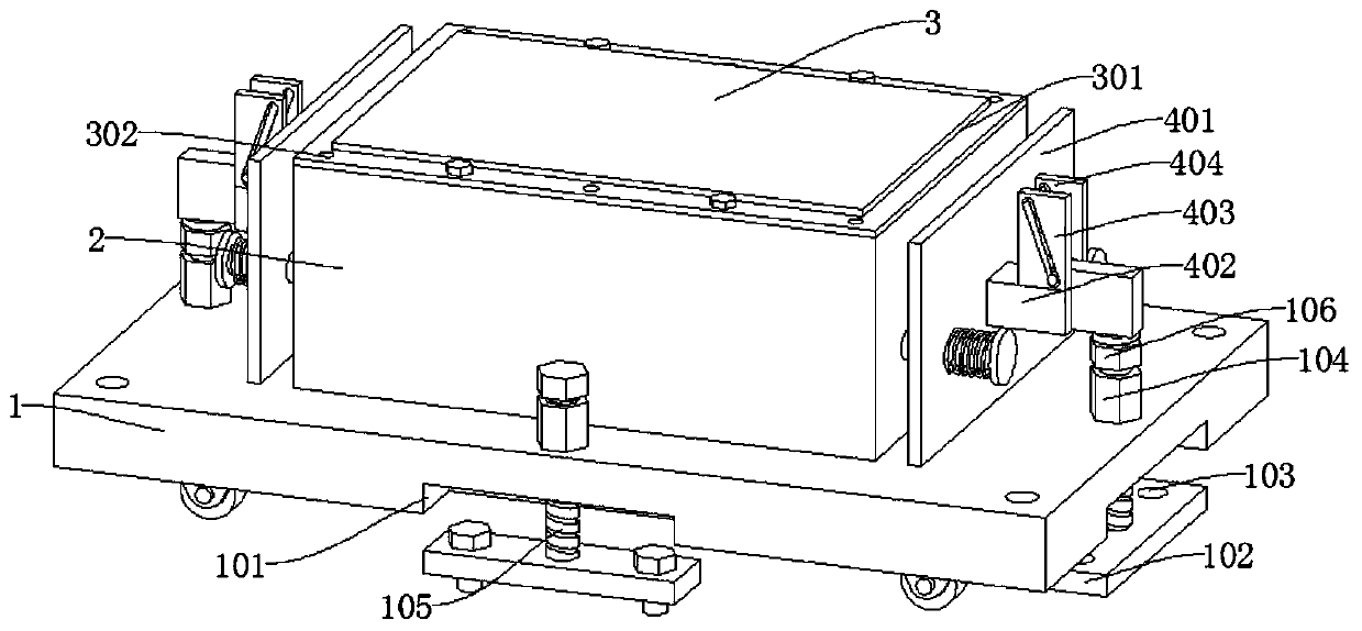
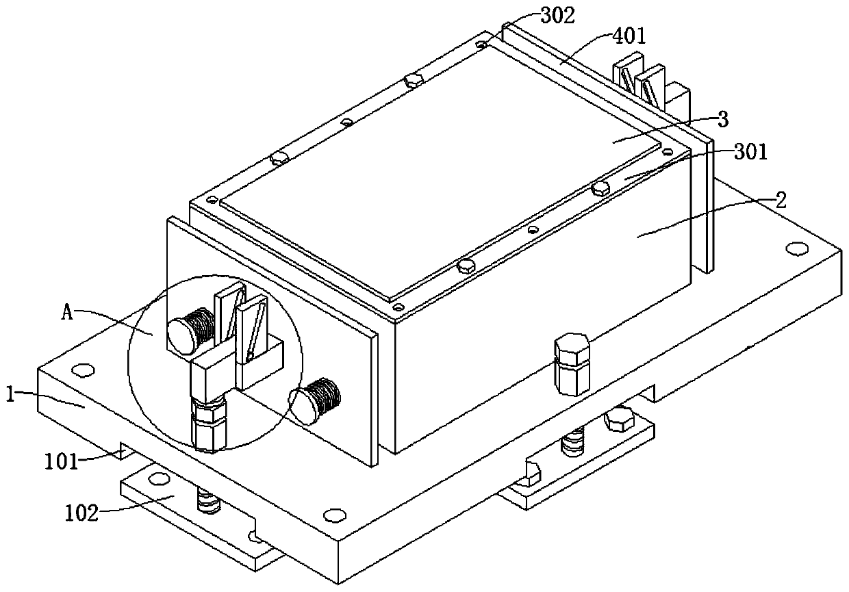
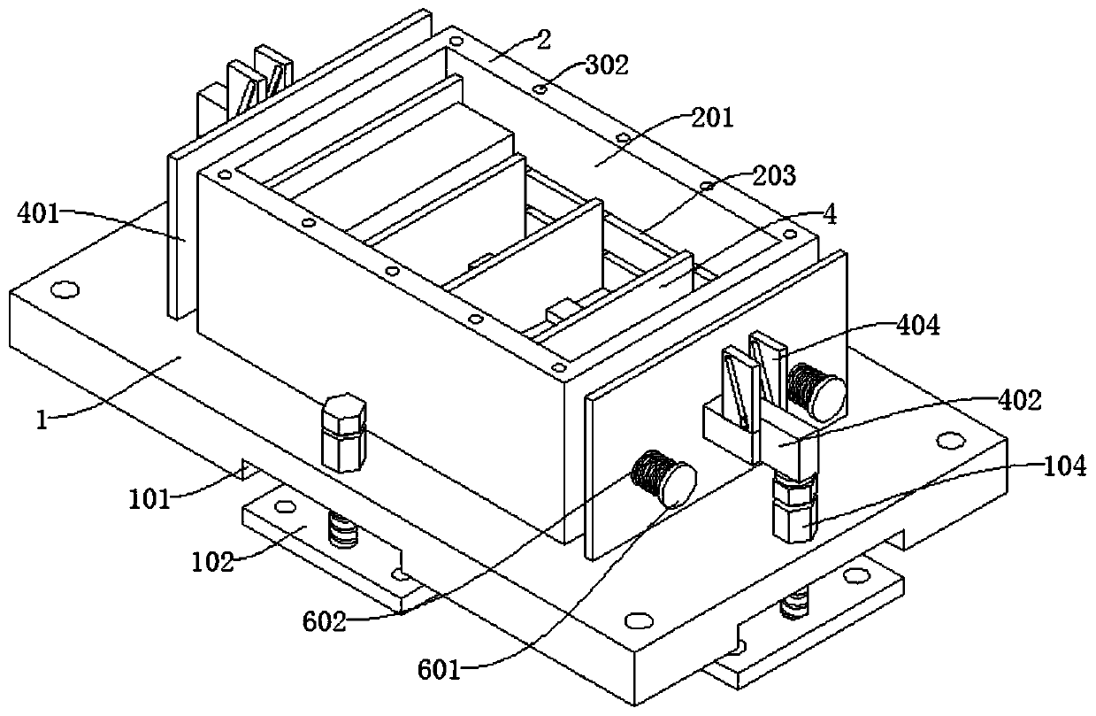
[0034] Reference Figure 1-8 , A battery installation and transportation device for a new energy vehicle, comprising a bottom plate 1, and a first groove 101 and a second groove are provided on the bottom of the bottom plate 1;
[0035] A mounting plate 102 is connected in the first groove 101, the top of the mounting plate 102 is rotatably connected with a threaded rod 105, the top outer wall of the bottom plate 1 is fixedly connected with a nut seat 104 threadedly connected with the threaded rod 105, and the top of the threaded rod 105 is connected with Slider 5;
[0036] The top of the bottom plate 1 is fixedly connected with a battery frame 2, a sliding board 4 is slidably connected in the battery frame 2, and the end of the sliding board 4 away from the sliding board 4 passes through the battery frame 2 and is connected with a sliding rod 402. The sliding rod 402 and the outer wall of the sliding block 5 are both Equipped with inclined surfaces;
[0037] A roller 107 is connec...
Embodiment 2
[0042] Reference Figure 1-8 , A battery installation and transportation device for a new energy vehicle, which is basically the same as the first embodiment. Furthermore, the outer wall of the fixed block 403 is also provided with a chute 405, and the outer walls of both sides of the slider 5 are connected to the limit rod 501, The limit rod 501 is slidably connected in the chute 405; by setting the chute 405, the slider 5 can be moved conveniently, so that the slider 5 can be easily matched with the slider 402. At the same time, the limit rod 501 can adjust the slider 5 The limit position, so that it will not rotate with the rotation of the threaded rod 105.
[0043] The top outer wall of the bottom plate 1 is also fixedly connected with a fixed plate 401, and the sliding rod 402 is slidably connected to the fixed plate 401; the fixed plate 401 can fix and support the sliding rod 402, which is convenient for the sliding rod 402 to drive the sliding plate 4 to slide.
[0044] The...
Embodiment 3
[0046] Reference Figure 1-8 , A battery installation and transportation device for a new energy vehicle is basically the same as the first embodiment. Furthermore, the inner wall of the battery frame 2 is provided with a third groove 201, and the sliding plate 4 is slidably connected in the third groove 201.
[0047] The bottom of the battery frame 2 is fixedly connected with a heat dissipation plate 202, the heat dissipation plate 202 is provided with a heat dissipation hole 2021, the bottom of the bottom plate 1 is provided with a round hole 108, and a heat dissipation fan 103 is connected to the round hole 108; High temperature damages the battery.
[0048] The top outer wall of the heat dissipation plate 202 is provided with a cross bar 204, the cross bar 204 is slidably connected with a partition 205, the inner wall of the third groove 201 is provided with a long groove 203, and the side wall of the partition 205 is slidably connected with the long groove 203 The bumps; the ...
PUM
 Abstract
Description
Claims
Application Information
 - R&D
- Intellectual Property
- Life Sciences
- Materials
- Tech Scout
- Unparalleled Data Quality
- Higher Quality Content
- 60% Fewer Hallucinations
Browse by: Latest US Patents, China's latest patents, Technical Efficacy Thesaurus, Application Domain, Technology Topic, Popular Technical Reports.
© 2025 PatSnap. All rights reserved.Legal|Privacy policy|Modern Slavery Act Transparency Statement|Sitemap|About US| Contact US: help@patsnap.com


