Rotary automatic lifting handrail

An automatic lifting and rotating lifting technology, which is applied to other seating furniture, chairs, stools, etc., can solve the problems of complex lifting and adjusting structure of armrests, high production and maintenance costs, and inaccurate positioning, so as to achieve simple structure and prolong service life , the effect of convenient operation

Active Publication Date: 2020-02-25
东莞市星火齿轮有限公司
View PDF9 Cites 2 Cited by
  • Summary
  • Abstract
  • Description
  • Claims
  • Application Information

AI Technical Summary

Problems solved by technology

[0002] With the rapid development of social economy and the continuous improvement of people's living standards, in order to obtain a more comfortable working environment, it has become a common technical means for people to configure corresponding hand rests on sofas and other seats. For example, in some meeting rooms, The sofas used in environments such as lecture halls and rest areas are equipped with manually adjustable hand rests, which can only be adjusted properly through human operation, and cannot really meet people's actual use needs. In order to overcome the manual The problem of adjustment, there are some armrests on the market that can realize automatic lifting, but the lifting and adjusting structure of the existing chairs for the armrests is complicated, its production and maintenance costs are high, and the operation is not flexible, difficult to operate, and the positioning is not accurate, etc., which is not convenient. people use

Method used


Image

  • Rotary automatic lifting handrail
  • Rotary automatic lifting handrail
  • Rotary automatic lifting handrail

Examples


specific Embodiment approach

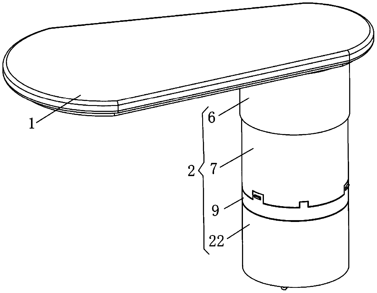
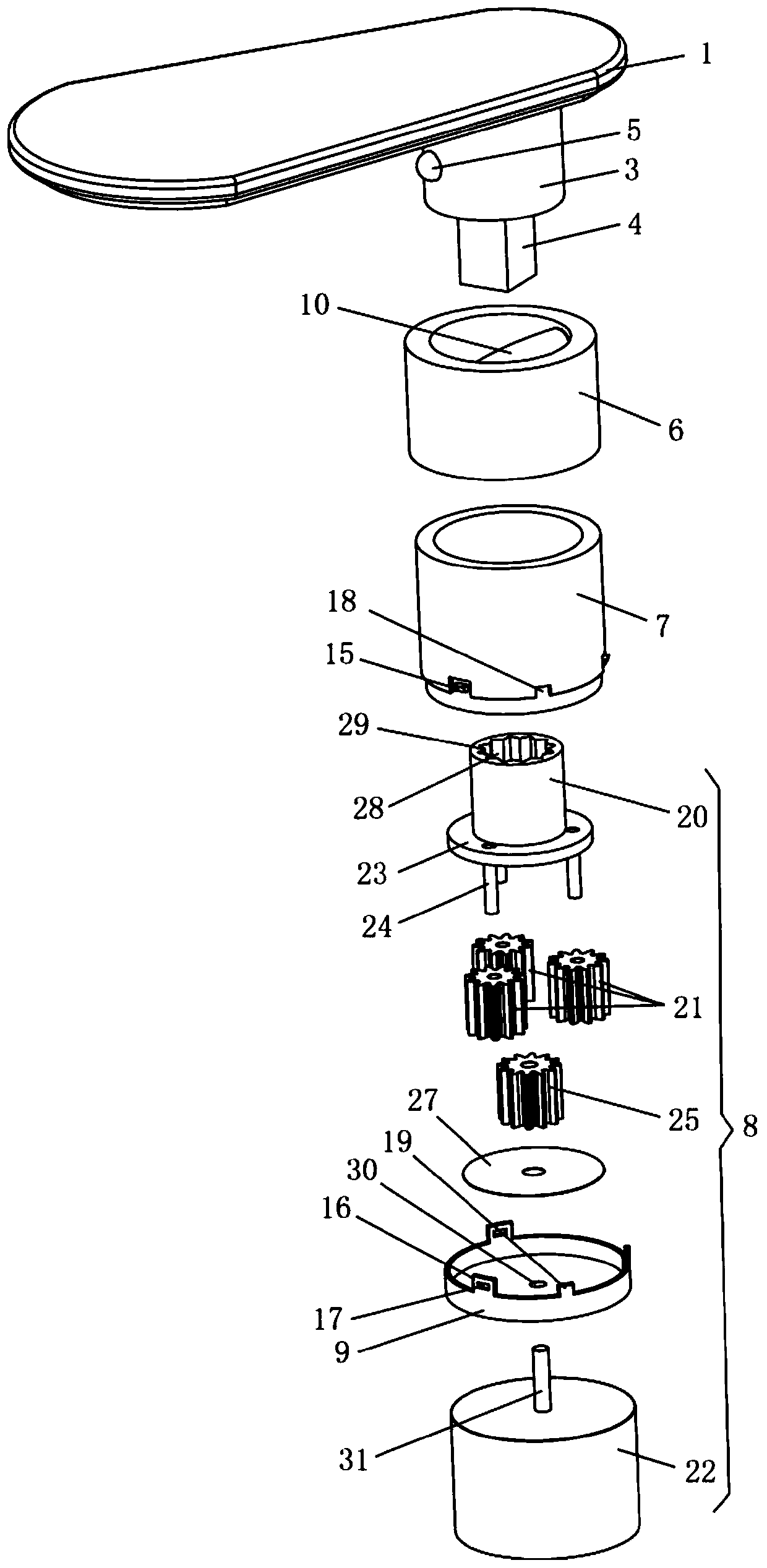
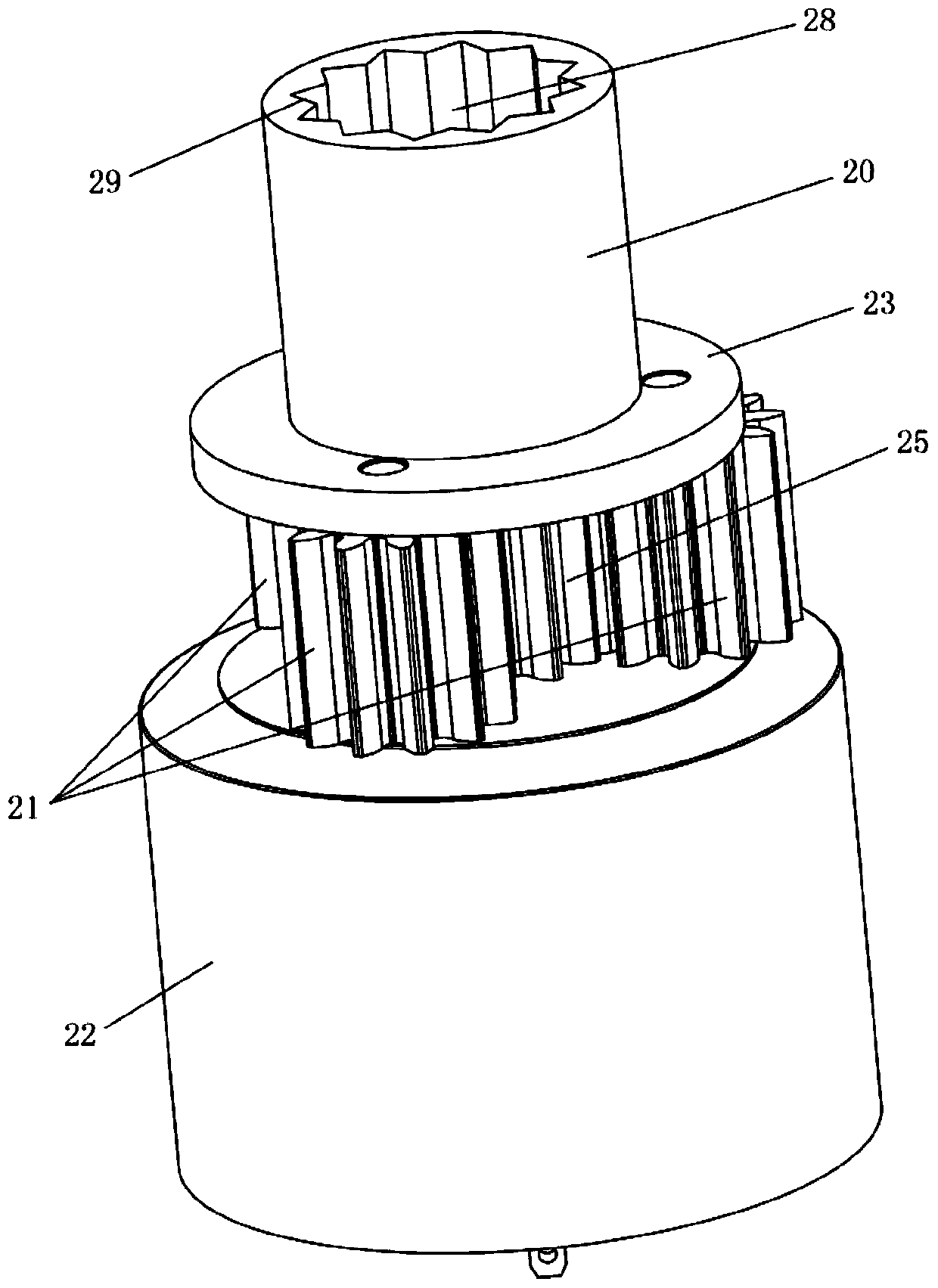
[0026] like Figure 1-7 As shown, a rotary automatic lifting handrail includes a hand rest 1 and a rotating lifting device 2, the bottom of the hand rest 1 is provided with an engaging block 3, and the bottom of the engaging block 3 is provided with a transmission block 4. The outer wall of the block 3 is provided with at least one outwardly protruding steel ball 5. The rotary lifting device 2 includes an orbital ring 6, an inner ring gear 7, a transmission mechanism 8 and a fixed seat 9. The orbital ring 6 is installed on On the inner ring gear 7, the transmission mechanism 8 is connected to the inner ring gear 7, the fixed seat 9 is fixedly mounted on the inner ring gear 7, and the track ring 6 is provided with a The ball 5 cooperates with the sliding guide rail 10, the first and last ends of the sliding guide rail 10 are distributed on the inner side wall of the track ring 6, and the hand rest 1 is rotatably mounted on the connecting block 3 In the track ring 6, the steel ...


PUM


Abstract

The invention relates to a rotary automatic lifting handrail. The rotary automatic lifting handrail comprises a hand support and a rotary lifting device, wherein the hand support is provided with a connecting block and a transmission block; a steel ball is arranged on the outer side wall of the connecting block; the rotary lifting device comprises a track ring, an inner gear ring, a transmission mechanism and a fixed seat; the track ring is installed on the inner gear ring; the transmission mechanism is in transmission connection with the inner gear ring; the fixed seat is installed on the inner gear ring; the track ring is provided with a sliding guide rail with two ends distributed on the inner side wall of the track ring and having uneven heights; the hand support is installed in the track ring through the connecting block; the steel ball is slidably embedded in the sliding guide rail; and the transmission block is in transmission connection with the transmission mechanism. The rotary automatic lifting handrail has the beneficial effects that a miniature planetary transmission system is arranged on a traditional handrail, so that automatic rotation and lifting functions are achieved; the rotating structure adopts guide rail type motion, the friction of the steel balls is small, the contact area is increased, the stability and the accuracy are improved; and the lifting structure adopts an inner gear meshing principle, the transmission block and the inner gear ring are meshed with each other to drive the hand support to rotate, so that the stable performance is improved.

Description

technical field [0001] The invention relates to the technical field of chair armrests, in particular to a rotary automatic lifting armrest on a sofa that can be electrically lifted and lowered. Background technique [0002] With the rapid development of social economy and the continuous improvement of people's living standards, in order to obtain a more comfortable working environment, it has become a common technical means to configure corresponding hand rests on sofas and other seats. For example, in some conference rooms, The sofas used in environments such as lecture halls and rest areas are equipped with manually adjustable hand rests, which can only be adjusted properly through human operation, and cannot really meet people's actual use needs. In order to overcome the manual The problem of adjustment, there are some armrests that can realize automatic lifting on the market, but the lifting and adjusting structure of the existing chairs for the armrests is complex, its ...

Claims


Application Information

Patent Timeline
Patent Type & Authority Applications(China)
IPC IPC(8): A47C7/54
CPCA47C7/541Y02B50/00
Inventor 任继华李静向仕春
Owner 东莞市星火齿轮有限公司
Why Eureka
Try Eureka