Eureka AIR delivers breakthrough ideas for toughest innovation challenges, trusted by R&D personnel around the world.

Capacitor clamping type three-level direct-current converter adopting asymmetric bidirectional switch

A two-way switch, capacitor clamping technology, applied in the direction of DC power input conversion to DC power output, high-efficiency power electronic conversion, adjustment of electrical variables, etc. Balance, mid-point potential imbalance and other issues, to reduce current stress, improve reliability, reduce losses

Pending Publication Date: 2020-02-21
SHAANXI UNIV OF SCI & TECH
View PDF0 Cites 0 Cited by
  • Summary
  • Abstract
  • Description
  • Claims
  • Application Information

AI Technical Summary

Problems solved by technology

[0003] However, the traditional three-level DC-DC converter has the problem of unbalanced current and the unbalanced midpoint potential of the input capacitor, because when the charging and discharging times of the upper and lower switching tubes are not equal, the upper and lower switching tubes will appear. If the charging and discharging times of two input capacitors are not equal, the inherent disadvantage of midpoint potential imbalance will appear.
Especially when the duty cycle is reduced, the current of the input capacitor and the switch tube will be extremely unbalanced, which will reduce the reliability of the entire circuit and increase the stress of the switch tube

Method used


Image

  • Capacitor clamping type three-level direct-current converter adopting asymmetric bidirectional switch
  • Capacitor clamping type three-level direct-current converter adopting asymmetric bidirectional switch
  • Capacitor clamping type three-level direct-current converter adopting asymmetric bidirectional switch

Examples


Embodiment Construction

[0028] In order to make the purpose and technical solution of the present invention clearer and easier to understand. The present invention will be further described in detail below in conjunction with the drawings and embodiments. The specific embodiments described here are only used to explain the present invention, not to limit the present invention.

[0029] In the description of the present invention, it should be understood that the terms "first" and "second" are used for description purposes only, and cannot be interpreted as indicating or implying relative importance or implicitly indicating the quantity of indicated technical features. Thus, a feature defined as "first" and "second" may explicitly or implicitly include one or more of these features. In the description of the present invention, unless otherwise specified, "plurality" means two or more. In the description of the present invention, it should be noted that unless otherwise specified and limited, the term...


PUM


Abstract

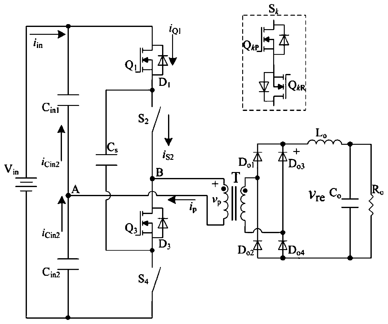
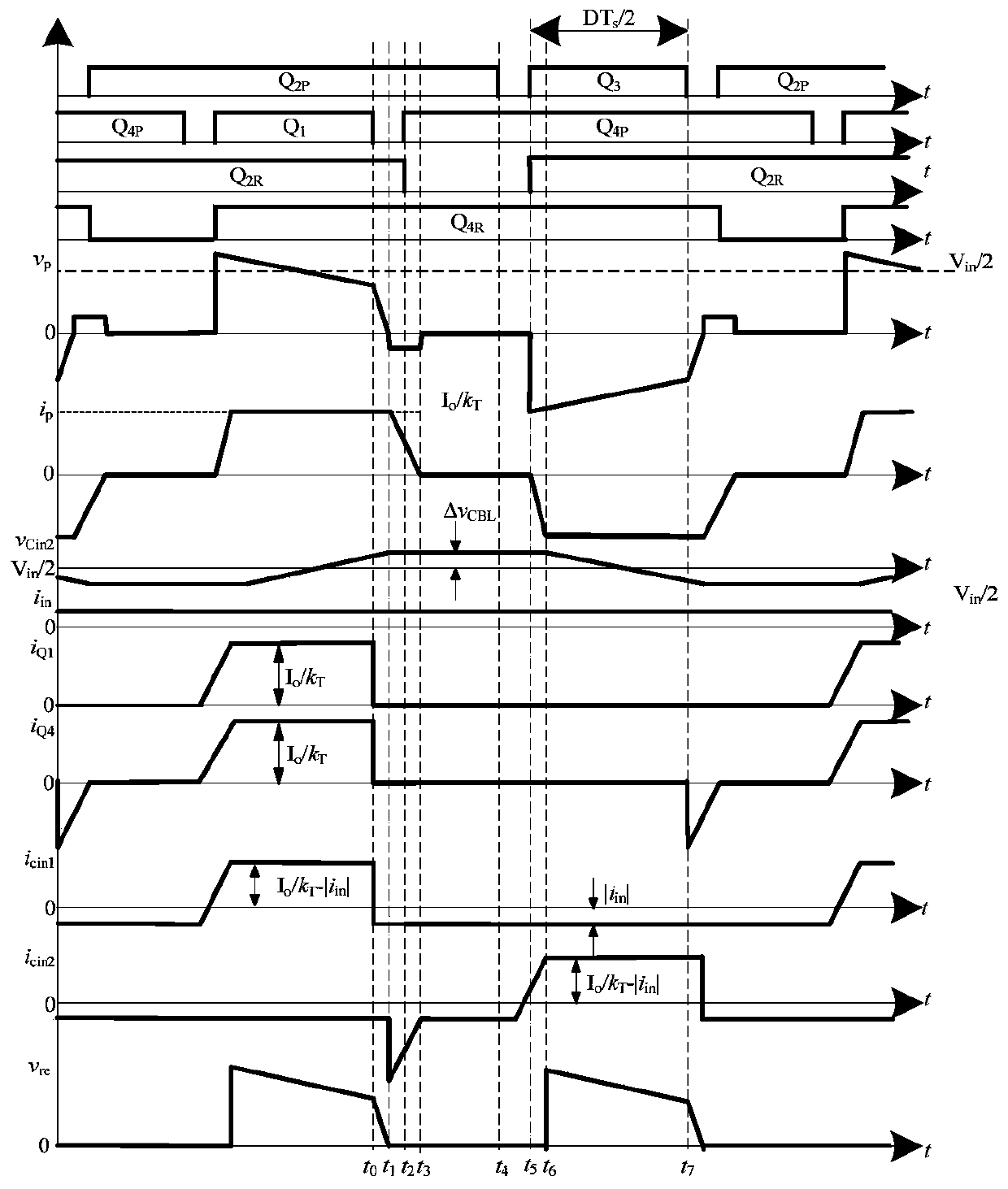
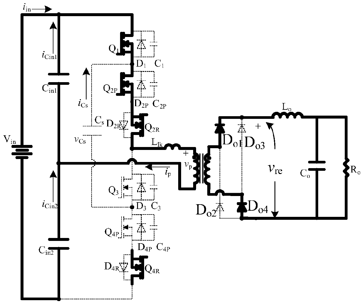
The invention discloses a capacitor clamping type three-level direct-current converter adopting an asymmetric bidirectional switch. The capacitor clamping type three-level direct-current converter comprises a voltage source Vin, a voltage dividing capacitor Cin1, a voltage dividing capacitor Cin2, a primary side inversion unit and a transformer T. Input high-voltage direct current obtains alternating-current square waves on the primary side of the transformer by controlling on and off of a switch tube, passes through the transformer T, then is connected with a rectifier bridge on the secondaryside of the transformer, and then outputs direct-current voltage through the filter circuit. The problem of unbalanced current existing in an existing three-level circuit is solved. The turn-off current of a switching device in the circuit is reduced. The current stress of the switch tube is reduced. Zero-voltage zero-current turn-on and turn-off of the switch tube are achieved. The loss of the whole circuit is reduced. The reliability of the circuit is enhanced.

Description

technical field [0001] The invention belongs to the technical field of high-voltage DC converters, in particular to a capacitor-clamped three-level DC converter using an asymmetric bidirectional switch. Background technique [0002] Since high-performance high-input power DC converters have great potential in market applications, three-level DC-DC converters have become the subject of extensive research. Compared with the traditional two-level DC-DC converter, the three-level DC-DC converter has the advantages of large output capacity, high output voltage, and small current harmonic content. [0003] However, the traditional three-level DC-DC converter has the problem of unbalanced current and the unbalanced midpoint potential of the input capacitor, because when the charging and discharging times of the upper and lower switching tubes are not equal, there will be two If the charging and discharging times of two input capacitors are not equal, the inherent disadvantage of m...

Claims


Application Information

Patent Timeline
IPC IPC(8): H02M3/335H02M7/487
CPCH02M3/33569H02M7/487H02M1/0058Y02B70/10
Inventor 石勇李启凡宋扬冯浪浪
Owner SHAANXI UNIV OF SCI & TECH
Why Eureka
Eureka Blog
Learn More