An auxiliary heat dissipation device for a power distribution cabinet in a power distribution room

A technology for assisting heat dissipation and power distribution cabinets, which is applied in the cooling/ventilation of substations/switchgears, substation/switch layout details, electrical components, etc. Dust, difficult to rotate, etc.

Active Publication Date: 2021-03-02
国网河南省电力公司长垣市供电公司 +2
View PDF1 Cites 0 Cited by
  • Summary
  • Abstract
  • Description
  • Claims
  • Application Information

AI Technical Summary

Problems solved by technology

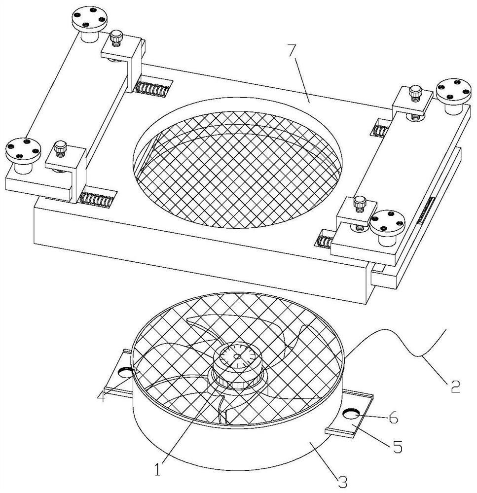
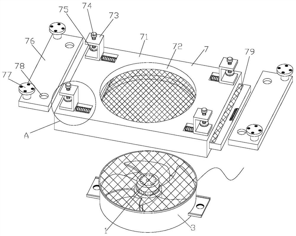
[0004] In order to overcome the deficiencies of the existing technology, a power distribution cabinet auxiliary heat dissipation device for a power distribution room is proposed, which solves the problem that when the heat dissipation fan in the heat dissipation device needs to be disassembled and repaired after being damaged, the fan is usually bolted to the power distribution cabinet. Internally, the bolts are easy to rust and difficult to rotate after long-term use. At the same time, the air inlet port of the cooling fan is easy to accumulate dust after long-term use. The dust process makes the heat dissipation effect of the cooling fan worse. A large workload, which brings inconvenience to the work

Method used


Image

  • An auxiliary heat dissipation device for a power distribution cabinet in a power distribution room
  • An auxiliary heat dissipation device for a power distribution cabinet in a power distribution room
  • An auxiliary heat dissipation device for a power distribution cabinet in a power distribution room

Examples


Embodiment Construction

[0028] The technical solutions of the present invention will be further described below in conjunction with the accompanying drawings and through specific implementation methods.

[0029] Wherein, the accompanying drawings are only for illustrative purposes, showing only schematic diagrams, rather than physical drawings, and should not be construed as limitations on this patent; in order to better illustrate the embodiments of the present invention, some parts of the accompanying drawings will be omitted, Enlargement or reduction does not represent the size of the actual product; for those skilled in the art, it is understandable that certain known structures and their descriptions in the drawings may be omitted.

[0030] In the drawings of the embodiments of the present invention, the same or similar symbols correspond to the same or similar components; , "inner", "outer" and other indicated orientations or positional relationships are based on the orientations or positional ...


PUM


Abstract

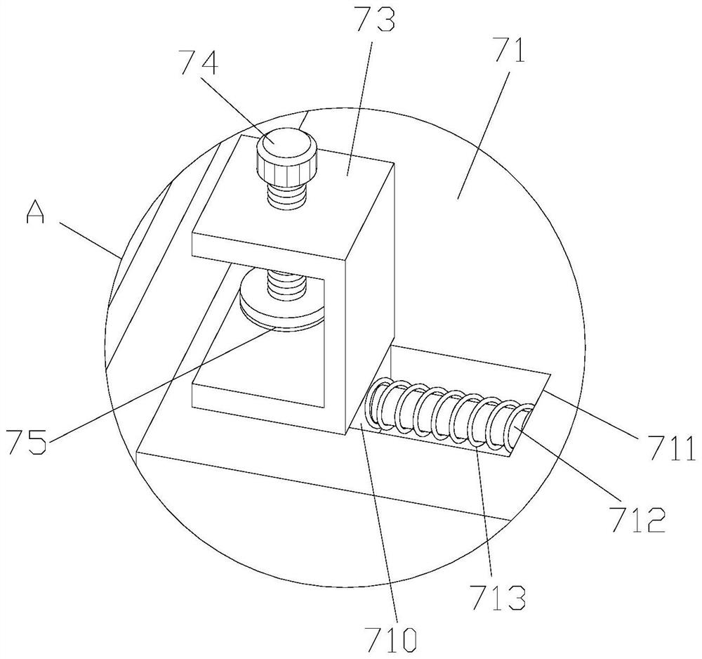
The invention discloses an auxiliary cooling device for a power distribution cabinet used in a power distribution room. The structure includes a cooling fan body, a power cord and a connecting mechanism. The connecting mechanism is provided on the outside of the protective shell, and the positioning plate is driven by a rotating screw to rotate. , so that the screw drives the positioning plate to rotate and rise away from the inside of the positioning groove, and then push the U-shaped plate radially to the through hole, so that the U-shaped plate drives the slider to slide inside the chute, and the U-shaped plate is separated from the outside of the connecting plate, so that the Remove the cooling fan, and turn over the top plate to maintain the cooling fan body. At the same time, you can pull the pull block to the right to remove the old replacement filter, and then insert the slide plate with the new replacement filter into the slot for placement , to quickly disassemble and repair the damaged cooling fan, improve work efficiency, and quickly replace the filter screen that has accumulated a lot of dust, improve the heat dissipation effect, and bring convenience to the work.

Description

technical field [0001] The invention relates to the technical field of heat dissipation devices, in particular to an auxiliary heat dissipation device for a power distribution cabinet used in a power distribution room. Background technique [0002] The switch distribution cabinet is the most important power supply equipment in the existing grid power distribution room. There are generally transformers, high and low voltage equipment inside the grid power distribution room. These devices are composed of components, and these devices are working In the process of use, currents and heat are generally generated, which will easily cause the temperature inside the grid power distribution room to be higher than the normal temperature outside, especially in hot summer, when the temperature is relatively high. The temperature will be higher, because these components are electrical equipment, often bring a lot of uncertainty, which brings a lot of potential safety hazards to the elect...

Claims


Application Information

Patent Timeline
Patent Type & Authority Patents(China)
IPC IPC(8): H02B1/56
CPCH02B1/565
Inventor 夏安祥
Owner 国网河南省电力公司长垣市供电公司
Why Eureka
Try Eureka