A drainage device for water conservancy projects

A water conservancy engineering, horizontal technology, applied in water conservancy engineering, sea area engineering, dams, etc.

Active Publication Date: 2021-07-30
SHANDONG PROVINCE WATER CONSERVANCY BUREAU CO LTD
View PDF4 Cites 0 Cited by
  • Summary
  • Abstract
  • Description
  • Claims
  • Application Information

AI Technical Summary

Problems solved by technology

[0002] In water conservancy projects, when floods occur, the general approach is to use anti-blocking methods, which can only play a temporary role in dealing with floods, in order to guide the water out of the river when floods occur, so this Invention proposes a drainage device for water conservancy projects

Method used


Image

  • A drainage device for water conservancy projects
  • A drainage device for water conservancy projects
  • A drainage device for water conservancy projects

Examples


Embodiment 1

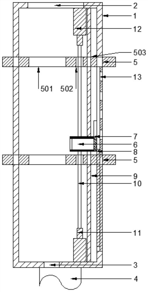
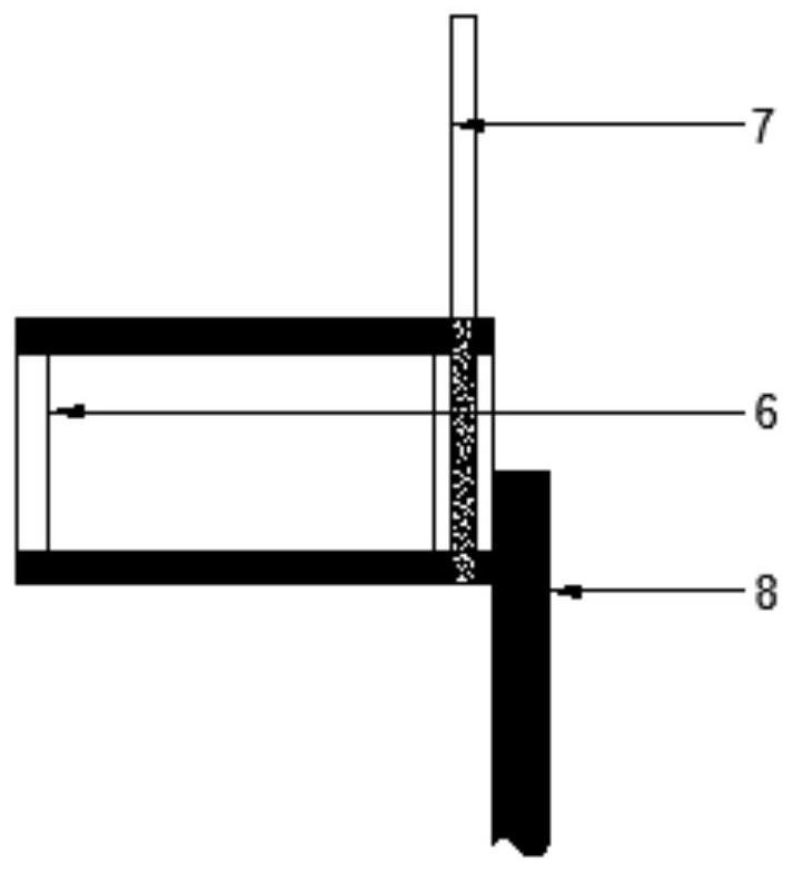
[0019] see Figure 1-3 , a drainage device for water conservancy projects, comprising a casing 1, a pipe 4 and a lifting assembly, the uppermost end of the casing 1 is provided with an upper hole 2, the lowermost end of the casing 1 is provided with a lower hole 3, and the pipe 4 is installed on the bottom of the casing 1 The lower end of the lower hole 3, the lifting assembly includes a horizontal mounting plate 5, a lifting member 6, a lifting plate 7, a vertical mounting plate 8, a fixed mounting rod 9, a connecting rod 10, a lower telescopic rod 11 and an upper telescopic rod 12; The number of 5 is two, and they are horizontally fixedly installed on the upper and lower positions of the housing 1. The horizontal mounting plate 5 is sequentially provided with a first hole 501, a second hole 502 and a third hole 503 on a straight line. The lower bottom plate is fixedly installed with the lower telescopic rod 11, the upper bottom plate of the housing 1 is fixedly mounted with ...

Embodiment 2

[0027] In this embodiment, as an improvement of Embodiment 1, the connecting rod 10 is installed inside the housing 1 through an elastic member, and the connecting rod 10 is installed inside the housing 1 through an elastic member, so that the connecting rod 10 can be used for water drainage in hydraulic engineering. The cushioning effect in the device has been improved.

[0028] The working principle of the present invention is: the drainage device for water conservancy projects is connected with the river channel through the pipeline 4, when the flood occurs, the water level rises, the lifting member 6 rises, and the lifting plate 7 and the vertical mounting plate 8 are driven to rise, when the lifting member 6 When rising to the upper horizontal mounting plate 5 installed on the shell 1, the lifting plate 7 slides downward, the right side of the lifting part 6 is emptied, and the water flows out through the side wall hole 13 to realize the transportation of water in the rive...


PUM


Abstract

The invention discloses a water drainage device for water conservancy engineering, which comprises a casing, a pipeline and a lifting assembly. The uppermost end of the casing is provided with an upper hole, the lowermost end of the casing is provided with a lower hole, and the pipeline is installed at the lower end of the lower hole of the casing. The lifting assembly includes a horizontal mounting plate, a lifting piece, a lifting plate, a vertical mounting plate, a fixed mounting rod, a connecting rod, a lower telescopic rod and an upper telescopic rod. When a flood occurs, the water level rises, and the lifting piece rises, driving the lifting plate and the vertical mounting plate to rise. When the lifting piece rises to the upper horizontal mounting plate installed on the shell, the lifting plate slides down, and the right side of the lifting piece is emptied. , the water flows out through the hole in the side wall to convey the water in the river to other places. When the water level drops, the lifting piece drops to the horizontal mounting plate installed under the shell, the lifting plate slides upward, and the right side of the lifting piece Closed, the water stops sending to the outside world. This makes it possible to automatically guide the water in the river out when a flood occurs.

Description

technical field [0001] The invention relates to the field of water conservancy projects, in particular to a drainage device for water conservancy projects. Background technique [0002] In water conservancy projects, when floods occur, the general approach is to use anti-blocking methods, which can only play a temporary role in dealing with floods, in order to guide the water out of the river when floods occur, so this The invention proposes a drainage device for water conservancy projects. Contents of the invention [0003] The purpose of the present invention is to provide a water drainage device for water conservancy engineering, so as to solve the problems raised in the above-mentioned background technology. [0004] To achieve the above object, the present invention provides the following technical solutions: [0005] A drainage device for water conservancy projects, comprising a casing, a pipe and a lifting assembly, the uppermost end of the casing is provided with...

Claims


Application Information

Patent Timeline
Patent Type & Authority Patents(China)
IPC IPC(8): E02B3/00E02B3/10
CPCE02B3/00E02B3/104
Inventor 牛之庚田茂志彭华高贞
Owner SHANDONG PROVINCE WATER CONSERVANCY BUREAU CO LTD
Why Eureka
Try Eureka