
Mowing head and mowing machine using same

A technology for mowers and mowers, applied in the field of mowers, can solve the problems of reducing user experience, time and energy consumption, and reducing work efficiency, so as to achieve the effect of increasing work efficiency and operating experience

Active Publication Date: 2020-02-21
NANJING CHERVON IND
View PDF9 Cites 5 Cited by
  • Summary
  • Abstract
  • Description
  • Claims
  • Application Information

AI Technical Summary

Problems solved by technology

At present, in order to wind the trimming rope to the spool, the user usually needs to remove the spool and manually wind the trimming rope. Obviously, such an operation is time-consuming and laborious, and reduces work efficiency.
For this reason, there is also a mowing head on the market that can wind the mowing rope to the spool without disassembling the spool. Wire
Due to professionalism, operating environment and other factors, the user needs to spend a lot of energy to align the inner threading hole of the bobbin with the outer threading hole of the grass head during the threading process, and during the threading process, because the grass rope itself is soft , so in the threading process, it is impossible to quickly pass the grass rope through one outer threading hole and out of the other outer threading hole, which is time-consuming and labor-intensive, and reduces user experience
Users still need to dismantle the spool frequently to achieve winding, which reduces work efficiency

Method used


Image

  • Mowing head and mowing machine using same
  • Mowing head and mowing machine using same
  • Mowing head and mowing machine using same

Examples


Embodiment 1

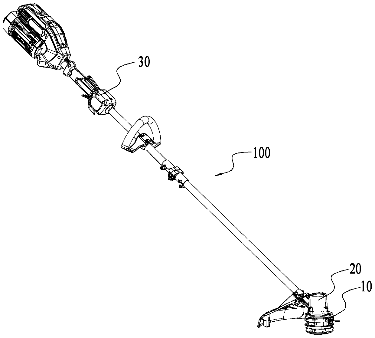
[0037] figure 1 Shown is a schematic structural view of a mowing machine 100 in an embodiment. In this embodiment, the mowing machine 100 includes a mowing head 10 , a driving device 20 and an operating device 30 .

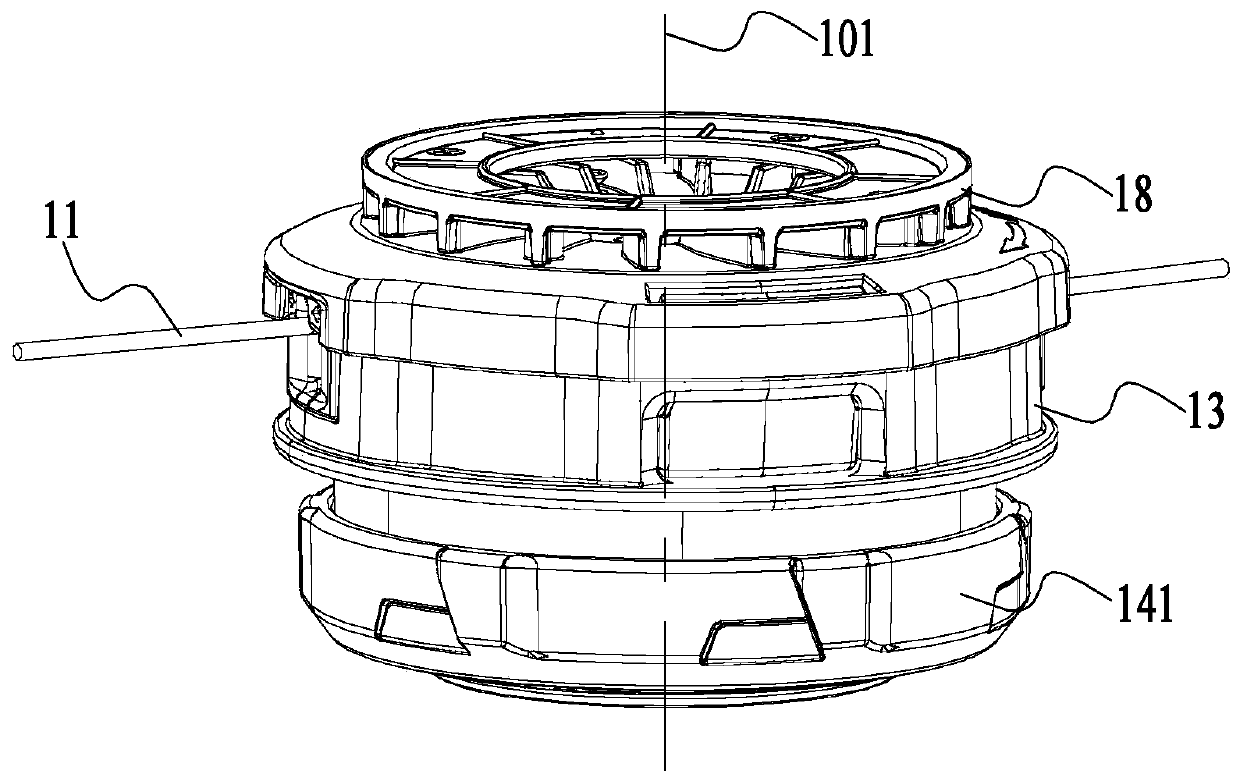
[0038] Such as figure 1 and figure 2 As shown, the driving device 20 can drive the mowing head 10 to rotate around the first axis 101, thereby driving the mowing rope 11 to rotate and cut vegetation. The operating device 30 is used for a user to operate to control the mower 100 .

[0039] The drive device 20 includes a motor and a drive shaft. Wherein, the driving shaft is connected to the mowing head 10 so as to drive the mowing head 10 to rotate around the first axis 101 .

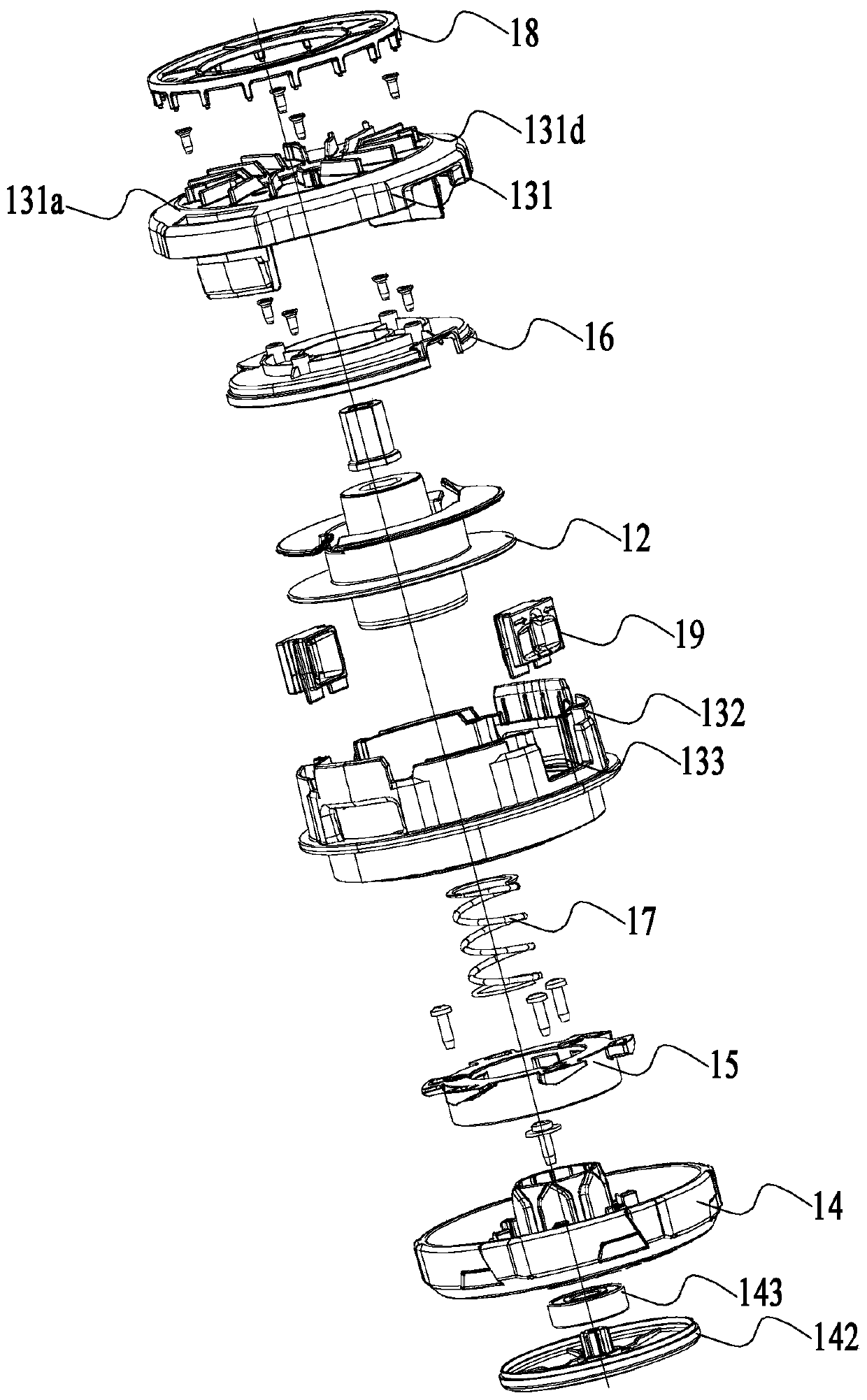
[0040] Such as figure 2 and image 3 As shown, the mowing head 10 includes a bobbin 12 and a head shell 13, the bobbin 12 is used to wind the mowing rope 11 and is accommodated in the head shell 13, the bobbin 12 is provided with a winding groove 127 (refer to Figure 7 );Such as ...

Embodiment 2

[0060] In an embodiment, the first guiding structure can also be connected to other positions of the head shell, such as Figure 13 to Figure 14 The structure of the grass cutting head in the second embodiment is shown. In this embodiment, the grass cutting head has the same driving device and operating device as in the first embodiment. The following only introduces the differences between the first embodiment and the first embodiment. structure.

[0061] Figure 13 The upper side and the lower side are defined in the middle. In this embodiment, the third guide 41 is connected to the second housing 42 through a fixing member, and is located between the bobbin 43 and the intermediate piece 44. The structure of the third guide 41 The structure is the same as that of the first guide structure 16 in Embodiment 1, only the position and orientation are different; the fourth guide 45 is located on the second stop portion of the bobbin 43, and the structure of the fourth guide 45 is...

Embodiment 3

[0063] In one embodiment, the mower has the same driving device and operating device as in the first embodiment, and only the different structures in this embodiment and the first embodiment will be introduced below. Such as Figure 15-Figure 17The mowing head 50 of the mowing machine in the third embodiment is shown. In this embodiment, the head shell includes a first housing part 51 and a second housing part 52 . The first guiding structure 521 is disposed on the second housing part 52, and the second housing part 52 is specifically an end away from the driving device. The second guiding structure 531 is disposed on the bobbin 53 and is disposed on a side close to the first guiding structure 521 . The first guiding structure 521 is fixedly connected or integrally formed with the second casing part 52 . The first guiding structure 521 has the same guiding area 521a through which the mowing rope can pass, a temporary storage area 521b for the mowing rope and a rotating area ...


PUM


Abstract

The invention discloses a mowing head and a mowing machine using the same. The mowing machine comprises the mowing head, a motor, a spool, a mowing head shell, a first guide structure and a second guide structure, wherein the motor drives the mowing head to rotate by using a first axis as the rotation axis; the spool is used for winding a mowing rope; the mowing head shell accommodates at least part of the spool; the first guide structure is formed on or connected to the mowing head shell and is used for guiding the mowing rope to penetrate the mowing head shell during threading; the second guide structure is formed on or connected to the spool; the mowing machine has a winding mode, the second guide structure is used for guiding the mowing rope to move and wind the spool through the relative rotation generated between the spool and the mowing head shell during winding. The mowing head and the mowing machine with the same are high in operation efficiency and good in user experience.

Description

technical field [0001] The invention relates to a garden tool, in particular to a mowing head and a mowing machine using the mowing head. Background technique [0002] As a kind of lawn trimming tool in a kind of garden class tool, mower has been widely paid attention to by people. Usually, the mowing machine includes a mowing head for mowing grass, and a spool for winding the mowing rope is arranged in the mowing head. At present, in order to wind the trimming rope to the spool, the user usually needs to remove the spool and manually wind the trimming rope. Obviously, such an operation is time-consuming and laborious, and reduces work efficiency. For this reason, there is also a mowing head on the market that can wind the mowing rope to the spool without disassembling the spool. However, the user still needs to manually align the outer wire hole of the mowing head with the inner threading hole of the spool to realize winding. Wire. Due to professionalism, operating envir...

Claims


Application Information

Patent Timeline
Patent Type & Authority Applications(China)
IPC IPC(8): A01D34/416
CPCA01D34/4161A01D34/416A01D34/4166A01D34/90
Inventor 彭明郭建朋任德宏
Owner NANJING CHERVON IND
Learn More