Explosion-proof electrical cabinet

A technology for electrical cabinets and cabinets, applied in the field of electrical cabinets, can solve problems such as narrow air expansion range, hinged plates are easy to be manually moved, and poor sealing effect, so as to achieve good resistance, increase sealing performance, and improve safety sexual effect

Active Publication Date: 2020-02-18
深圳市畅翔机电设备有限公司
View PDF21 Cites 3 Cited by
  • Summary
  • Abstract
  • Description
  • Claims
  • Application Information

AI Technical Summary

Problems solved by technology

[0005] In order to achieve the above object, the present invention provides the following technical solutions: an explosion-proof electrical cabinet, including a cabinet body, square grooves are opened on both sides of the cabinet body, and a hinged plate matching it is embedded inside the square groove, and the hinged plate and the cabinet The inner and outer surfaces of the body are even; two stretching devices are arranged on the side of the hinged plate close to the interior of the cabinet, and the stretching device is close to the top of the hinged plate. The stretching device includes a clamp and a fixed shaft, and the clamp and the hinge The plate is fixedly connected, the inner side of the card board is connected to the limit rod through the rotation of the fixed shaft, one end of the limit rod is fixedly connected with an elastic member, and a limit cylinder is arranged on the outside of the elastic member, one end of the limit cylinder is open, and the open end is far from the hinge with the clamp plate One side of the plate is in contact, and the top of the limit tube is fixedly connected with the top plate, which is fixedly connected with the inner wall of the cabinet at the top of the square groove; when working, due to the consideration of explosion-proof in the existing electrical cabinet, it is usually equipped with rotating hinges on both sides. One end of the hinged plate is hinged on the electrical cabinet, and the other end of the hinged plate can be deflected under the impact of the strong airflow inside the electrical cabinet to release the internal gas and prevent damage to the electrical cabinet, but this setting exists as follows The problem: the air can only be sprayed from the deflected end of the hinged plate, and the diffusion range when the air expands is relatively narrow. At the same time, the free end of the hinged plate can be rotated conveniently, and the sealing effect on the cabinet is not good. At the same time, the hinged plate is easy to be artificially Pulling, affecting the safety of personnel; therefore the main solution of the present invention is how to increase the diffusion range when the air expands, and ensure the sealing performance of the cabinet, and improve the safety during use; the specific measures and working process are as follows : By snapping the hinged plate into the square groove, it fits more closely with the cabinet and increases the sealing performance. At the same time, when the explosive gas inside the cabinet impacts the inner wall of the cabinet, it will push the hinged plate. Due to the action of the elastic parts, the hinged plate It can move horizontally, the hinge plate pulls the card plate and the fixed shaft, and the fixed shaft pulls the limit rod, and finally the elastic part is stretched. The hinge plate moves from the square groove and away from the cabinet body. Two motion states: one is that the gas pushes the bottom of the hinged plate to rotate, and the other is that the hinged plate continues to move away from the cabinet body. The finally expanded gas is not only ejected from the deflected position at the bottom of the hinged plate, but also from the gap between the top of the hinged plate and the cabinet body. The gap is sprayed out, which increases the diffusion range of the expansion gas. At the same time, the hinged plate is clamped at the position of the square groove, which is not easy to be pulled and improves the safety.

Method used


Image

  • Explosion-proof electrical cabinet
  • Explosion-proof electrical cabinet
  • Explosion-proof electrical cabinet

Examples


Embodiment Construction

[0020] In order to make the technical means realized by the present invention, creative features, goals and effects easy to understand, the following will further elaborate the present invention in conjunction with specific embodiments. figure 2 view direction.

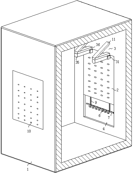
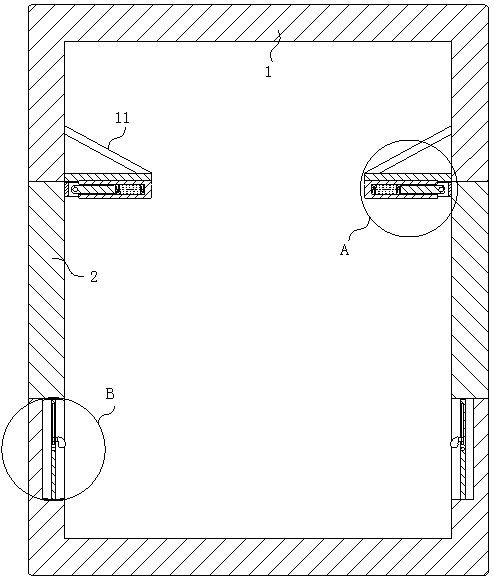
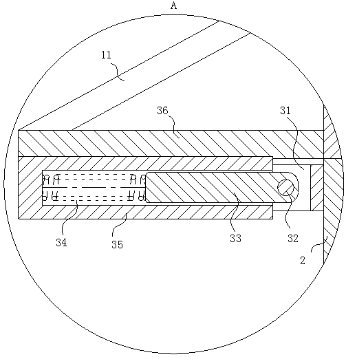
[0021] Such as Figure 1-4As shown, an explosion-proof electrical cabinet according to the present invention includes a cabinet body 1, and square grooves are opened on both sides of the cabinet body 1, and a hinged plate 2 matching it is embedded inside the square groove, and the hinged plate 2 is connected with the cabinet The inner and outer surfaces of the body 1 are flush; two stretching devices 3 are arranged on the side of the hinged plate 2 close to the inside of the cabinet body 1, and the stretching device 3 is close to the top of the hinged plate 2, and the stretching device 3 includes a clamping plate 31 And the fixed shaft 32, the clamping plate 31 is fixedly connected with the hinge plate 2, the inner ...


PUM


Abstract

The invention belongs to the technical field of electrical cabinets and specifically relates to an explosion-proof electrical cabinet, which includes a cabinet body. Square grooves are disposed on both sides of the cabinet body. Matching hinged plates are embedded in the square grooves, and are flush with the inner and outer surfaces of the cabinet body. The side of each hinged plate close to theinterior of the cabinet body is provided with two stretching devices. In the present invention, the hinged plates are embedded in the square groove by the stretching devices to fit the cabinet body closely so as to improve sealing performance. In addition, when an explosive gas inside the cabinet body impacts the inner wall of the cabinet body, the hinged plates are pushed and have two motion states after removed from the square grooves, in one of which two motion states, the gas drives the bottoms of the hinged plates to rotate, and in the other of of which two motion states, the hinged plates continues staying away from the cabinet body. Finally the expanded gas is ejected not only from the deflected positions on the bottoms of the hinged plates, but also from a gap between the tops of the hinged plates and the cabinet body, thereby expanding the diffusion range of the expanded gas, and the hinged plates are clamped to the positions of the square grooves, and are not easy to pull soas to improve safety.

Description

technical field [0001] The invention belongs to the technical field of electrical cabinets, in particular to an explosion-proof electrical cabinet. Background technique [0002] Explosion-proof electrical cabinets are often used in production sites where explosive gases are mixed, and explosion-proof distribution boxes will inevitably generate sparks during work. Once the sparks in the explosion-proof distribution box come into contact with explosive gases in the production site, it will It will cause an explosion, cause serious production accidents, and cause huge economic losses and casualties. Therefore, a hinged plate that can be deflected is installed on the electrical cabinet. When an explosion occurs inside, the strong airflow generated by the explosion will be deflected by pushing the hinged plate. Reduce the obstruction of air expansion and diffusion to the outside, and prevent the electrical cabinet from blocking the explosive gas, causing the electrical cabinet to...

Claims


Application Information

Patent Timeline
Patent Type & Authority Applications(China)
IPC IPC(8): H05K5/02H05K5/06
CPCH05K5/0217H05K5/069
Inventor 高海秀
Owner 深圳市畅翔机电设备有限公司
Why Eureka
Try Eureka