
Splicing structure of sliding contact line and sliding contact line thereof

A sliding contact line and splicing block technology, applied in the direction of connection, current collector, electrical components, etc., can solve the problem of inconvenient disassembly of the contact line, and achieve the effect of simple structure and good waterproof performance.

Pending Publication Date: 2020-02-18
GUANGZHOU BOYANG MACHINERY MFG CO LTD
View PDF0 Cites 1 Cited by
  • Summary
  • Abstract
  • Description
  • Claims
  • Application Information

AI Technical Summary

Problems solved by technology

On engineering equipment such as cranes, the chute lines are generally composed of segment structures, and the existing contact lines are inconvenient to disassemble

Method used


Image

  • Splicing structure of sliding contact line and sliding contact line thereof
  • Splicing structure of sliding contact line and sliding contact line thereof
  • Splicing structure of sliding contact line and sliding contact line thereof

Examples


Embodiment Construction

[0042] The specific embodiments of the present invention will be further described below in conjunction with the accompanying drawings. It should be noted here that the descriptions of these embodiments are used to help understand the present invention, but are not intended to limit the present invention. In addition, the technical features involved in the various embodiments of the present invention described below may be combined with each other as long as they do not constitute a conflict with each other.

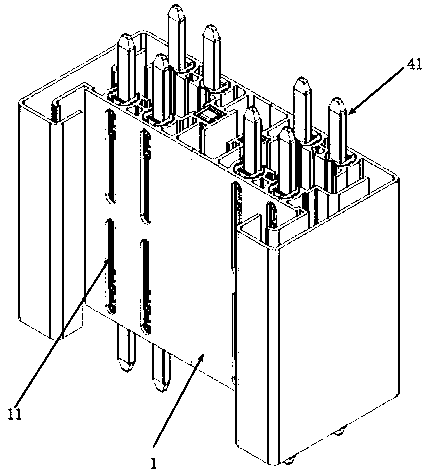
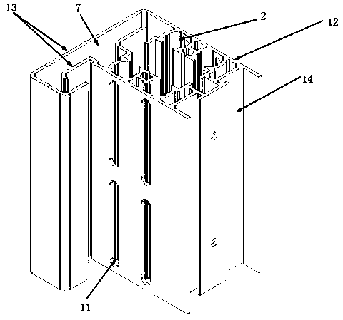
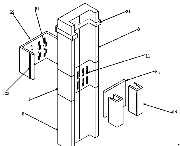
[0043] Such as Figures 1 to 13 As shown, a splicing structure of a trolley line includes a splicing block 1, and a plurality of installation grooves 2 are arranged in the splicing block 1; the installation grooves include a live wire, a neutral wire installation groove 2-1, and a ground wire installation groove 2-2 , There are four live wires and neutral wire installation slots 2-1, and one ground wire installation slot 2-2. The splicing block 1 is provided with a hol...


PUM


Abstract

The invention relates to the field of engineering equipment and in particular to a splicing structure of a sliding contact line. A splicing block is provided with a hollowed-out slot in communicationwith an installation slot. The installation slot is provided therein with a conductive slot. The conductive slot includes a sliding contact slot and an engagement slot. A stopping convex rib extends from the notch of the engagement slot. The splicing structure further includes a plug-in portion. The plug-in portion includes a plug-in board and a stopping board, which is connected to the plug-in board by a fastening bolt. The fastening bolt is provided with a convex edge. The plug-in board is disposed inside the engagement slot. The stopping board is also located inside the engagement slot andis abutted against the stopping convex rib. One end of the fastening bolt passes through the stopping board to be connected with the plug-in board, and the other end of the fastening bolt is located in the hollowed-out slot. The convex edge is abutted against the stopping convex rib. The splicing structure of the sliding contact line provided by the invention is stable in connection. The multiplesliding contact lines including the splicing structure are easy to disassemble and repair.

Description

technical field [0001] The invention relates to the field of engineering equipment, in particular to a splicing structure of a trolley line and the trolley line. Background technique [0002] Mobile equipment (mainly cranes, cranes, cranes, etc.) needs to change positions constantly due to movement. In each different position, mobile equipment must be able to obtain power at any time, otherwise it cannot continue to move. At this time, the sliding contact line came into being. Several conductors were laid in parallel along the running track of the mobile equipment, and the power was turned on. On the mobile equipment, a collector that could take electricity from the conductor was installed, so that , when the equipment moves, the collector operates synchronously with the equipment, and obtains power from the conductor at any time, and provides it to the equipment so that the equipment can continue to move. Usually, a collector is in contact with the trolley line on the mobi...

Claims


Application Information

Patent Timeline
Patent Type & Authority Applications(China)
IPC IPC(8): H01R41/00
CPCH01R41/00
Inventor 麦伟财
Owner GUANGZHOU BOYANG MACHINERY MFG CO LTD
Learn More