
Rotary transformer

A resolver and terminal technology, which is applied to electrical components, electromechanical devices, windings, etc., can solve problems such as poor reliability of resolvers, and achieve the effects of improving reliability, improving mechanical vibration resistance, and enhancing connection strength

Active Publication Date: 2020-02-14
UNITED AUTOMOTIVE ELECTRONICS SYST
View PDF4 Cites 0 Cited by
  • Summary
  • Abstract
  • Description
  • Claims
  • Application Information

AI Technical Summary

Problems solved by technology

[0005] The purpose of the present invention is to provide a rotary transformer to solve the problem of poor reliability of the rotary transformer in the prior art

Method used


Image

  • Rotary transformer
  • Rotary transformer
  • Rotary transformer

Examples


Embodiment Construction

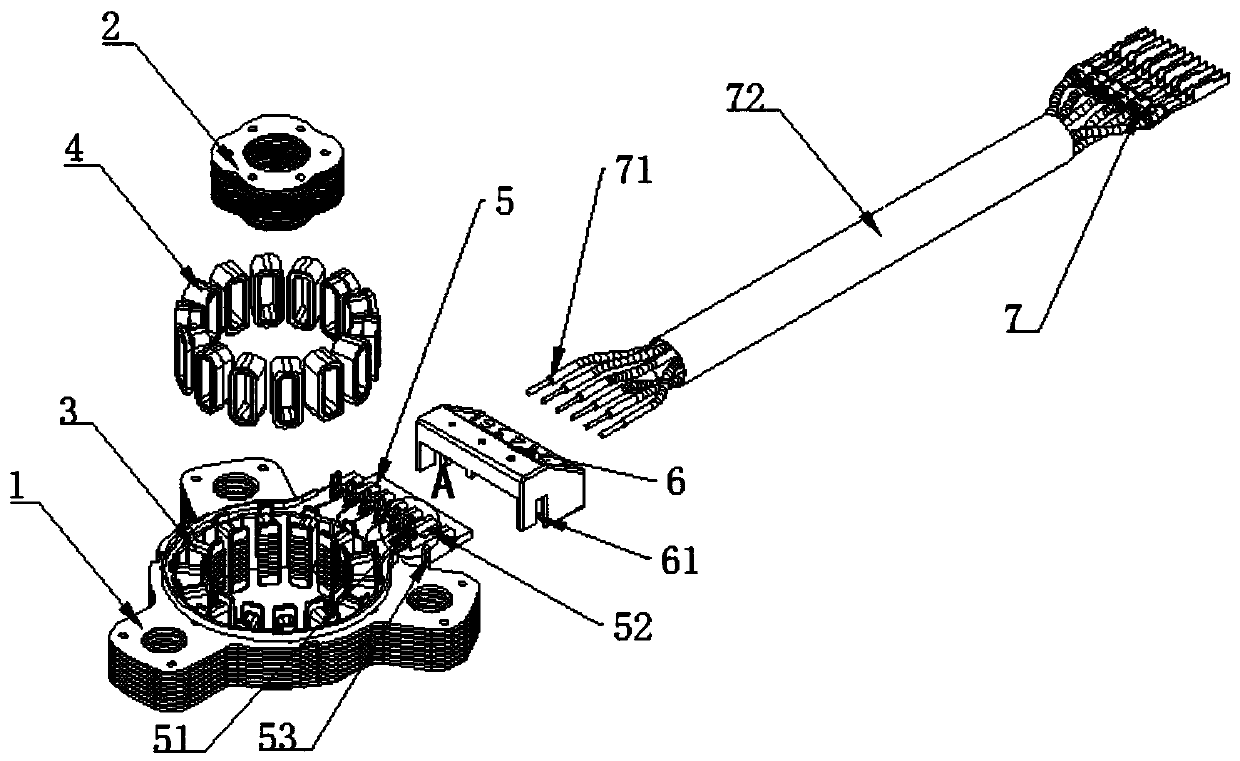
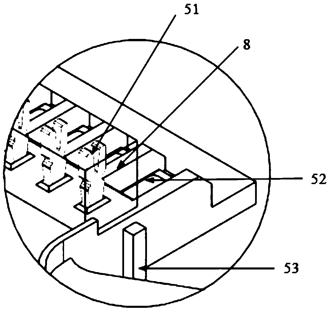
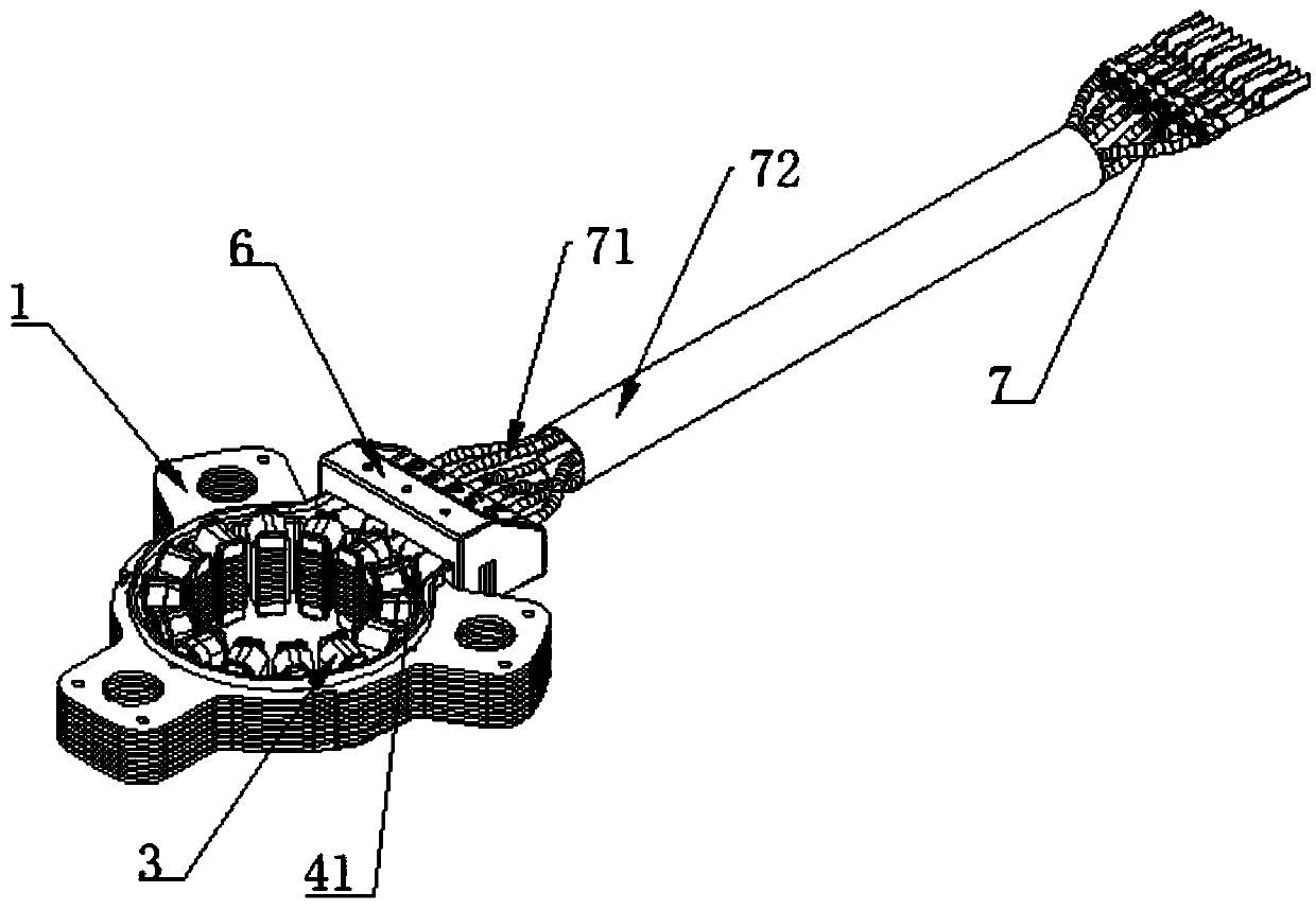
[0028] In order to make the purpose, advantages and characteristics of the present invention clearer, the following in conjunction with the attached Figure 1-8 The rotary transformer proposed by the present invention will be further described in detail. It should be noted that all the drawings are in a very simplified form and use imprecise scales, and are only used to facilitate and clearly assist the purpose of illustrating the embodiments of the present invention.

[0029] refer to Figure 1-8 , a rotary transformer, including a stator 1, an insulating frame 3, a winding 4 and a signal harness 7; the insulating frame 3 is located between the stator 1 and the winding 4; a junction box 5 is provided on the insulating frame 3 The junction box 5 is provided with a terminal 51; the lead-out line 41 of the winding 4 is connected to one end of the terminal 51, and the lead-out end of the signal line 71 in the signal harness 7 is connected to the other end of the terminal 51 con...


PUM


Abstract

The invention provides a rotary transformer, which is characterized in that signal lines and windings are both connected with binding posts so as to realize signal transmission between the signal lines and the windings and improve the reliability of signal transmission between the signal lines and the windings; a signal wire harness is fixedly connected with a protective cover, the impact force borne by the signal wire harness is transmitted to an insulating framework matched with the first protective cover through a first protective cover in the using process instead of being directly transmitted to a connecting point of the signal line and the binding post, the connecting strength of the connecting point is enhanced, and the mechanical vibration resistance of the connecting point of thesignal line and the binding post is improved; furthermore, the signal lines are fixedly connected with the protective cover in advance according to a certain sequence, so that connection errors occurred when the signal lines are connected with the binding posts are avoided, the connection sequence of the signal lines does not need to be further sorted during connection, the production efficiency is improved, and the production intensity is reduced.

Description

technical field [0001] The invention relates to the technical field of motors, in particular to a rotary transformer. Background technique [0002] Resolver (referred to as "resolver") is a kind of position sensor because it can work under harsh environmental conditions: such as mechanical vibration, high speed, high angular acceleration and noiseless requirements, as well as flammable, explosive, high and low temperature (-40 ~ 155 ℃) and other conditions, and has the advantages of high precision, high reliability, simple and compact structure, and low cost. It is widely used in the position sensor of power motors to detect the angle and speed of the motor rotor. [0003] The resolver used in the power motor is usually a reluctance resolver, which shows that all signal lines are wound on the stator, and no winding is arranged on the rotor. Its structure is mainly composed of the rotor pressed by silicon steel sheet, the stator pressed by silicon steel sheet, the insulating...

Claims


Application Information

Patent Timeline
Patent Type & Authority Applications(China)
IPC IPC(8): H02K3/50
CPCH02K3/50
Inventor 谢立贰谢英杰
Owner UNITED AUTOMOTIVE ELECTRONICS SYST
Learn More