
Display module and electronic device

A technology for display modules and electronic equipment, applied in the direction of instruments, nonlinear optics, optics, etc., can solve the problems of low performance of electronic equipment, achieve good optical performance, enhance support force, and prevent sags

Active Publication Date: 2020-02-14
VIVO MOBILE COMM CO LTD
View PDF8 Cites 6 Cited by
  • Summary
  • Abstract
  • Description
  • Claims
  • Application Information

AI Technical Summary

Problems solved by technology

[0005] The invention discloses a display module and electronic equipment to solve the problem of low performance of electronic equipment

Method used


Image

  • Display module and electronic device
  • Display module and electronic device

Examples


Embodiment Construction

[0018] In order to make the purpose, technical solution and advantages of the present invention clearer, the technical solution of the present invention will be clearly and completely described below in conjunction with specific embodiments of the present invention and corresponding drawings. Apparently, the described embodiments are only some of the embodiments of the present invention, but not all of them. Based on the embodiments of the present invention, all other embodiments obtained by persons of ordinary skill in the art without making creative efforts belong to the protection scope of the present invention.

[0019] The technical solutions disclosed by various embodiments of the present invention will be described in detail below in conjunction with the accompanying drawings.

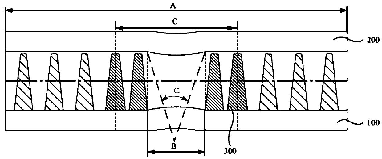
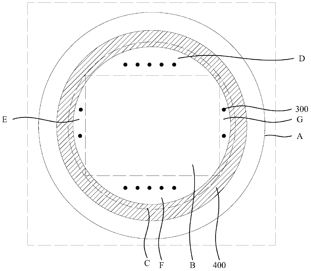
[0020] Such as Figure 1-Figure 2 As shown, the embodiment of the present invention discloses a display module, which is applied to electronic equipment with optical devices. The above-mentione...


PUM


Abstract

The invention discloses a display module and an electronic device. The display module comprises: a light transmitting cover plate, a first substrate, a second substrate and a first supporting column;the second substrate is located between the first substrate and the light transmitting cover plate, the second substrate has a first area and a second area, the second area is an area on the second substrate corresponding to the field range of an optical device, the first area is located in the second area, and the first area is an area on the second substrate corresponding to a light sensing areaof the optical device; and the first supporting column is disposed between the first substrate and the second substrate, at least a part of the first supporting column is located in a third area, andthe third area is an area excluding the first area in the second area. The display module is provided with the first supporting column in the third area, the first supporting column can avoid the light sensing area and can improve the supporting force of a light transmitting hole at the same time to effectively prevent the depression at the light transmitting hole, so that the light transmittinghole have better optical performance, and then the performance of the electronic device is improved.

Description

technical field [0001] The invention relates to the field of display technology, in particular to a display module and electronic equipment. Background technique [0002] With the advancement of technology and the development of electronic equipment, users' demand for full-screen electronic equipment is gradually increasing, and full-screen has gradually become a development trend. The installation location of components such as cameras, sensors, and receivers is the main factor restricting the development of full-screen displays. Taking the camera as an example, the existing solution is to set a driving mechanism in the casing of the electronic device, and the driving mechanism is connected with the camera to drive the camera to enter and exit the casing of the electronic device. However, this method requires a driving mechanism, which occupies a relatively large internal space of the housing of the electronic device. [0003] In order to solve the above problems, a light...

Claims


Application Information

Patent Timeline
IPC IPC(8): G02F1/1339G02F1/1335
CPCG02F1/13394G02F1/133512G02F1/13312G02F1/1333G02F1/133331G02F1/133302
Inventor 林华鑫程传波
Owner VIVO MOBILE COMM CO LTD
Learn More