Mine stone crushing device

A crushing device and stone material technology, which is applied in the direction of water/sewage multi-stage treatment, smoke and dust removal, grain processing, etc., can solve the problems affecting the health of the operator, damage to the surrounding environment, short service life, etc., to meet the needs of automatic transportation, Ensures cleanliness and improves smoothness

Inactive Publication Date: 2020-02-14
房文中
View PDF0 Cites 2 Cited by
  • Summary
  • Abstract
  • Description
  • Claims
  • Application Information

AI Technical Summary

Problems solved by technology

However, the crushing efficiency of the existing crushers for stones is low, and the crushing teeth need to be replaced frequently when crushing stones, and the service life is short; on the other hand, it is inevitable to generate a large amount of Dust pollutants, improper treatment of these pollutants will not only affect the health of the operator, but also cause great damage to the surrounding environment

Method used


Image

  • Mine stone crushing device
  • Mine stone crushing device
  • Mine stone crushing device

Examples


Embodiment 1

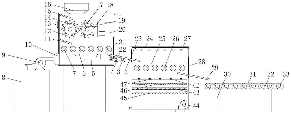
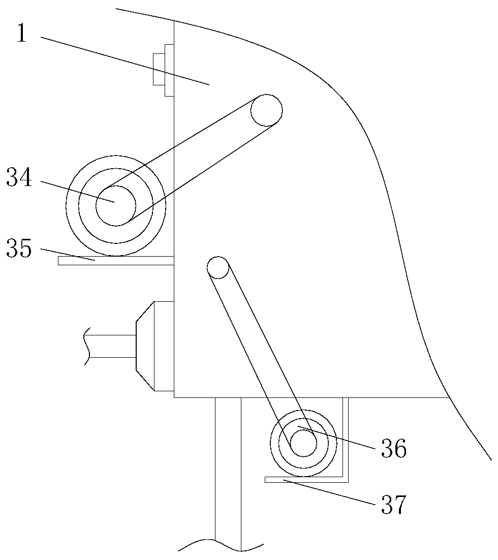
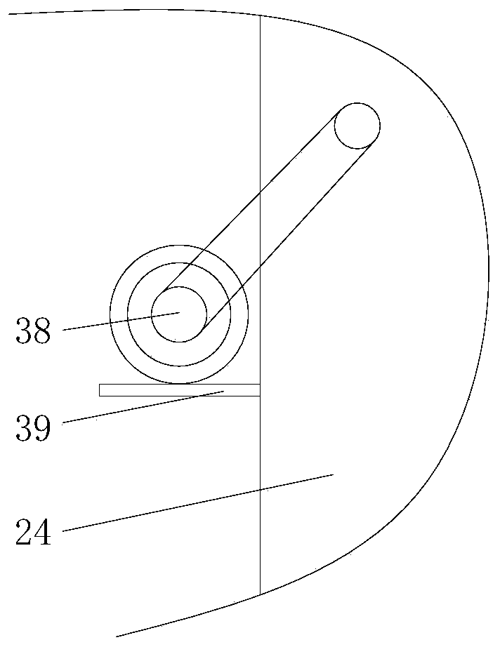
[0059] see Figure 1-6 , a crushing device for mine stone materials, comprising a crushing box 1, a dust collection box 8, a spray filter box 24 and a stone conveying platform 32, the left end of the crushing box 1 top is provided with a first feed port 16, and the left side of the crushing box 1 The upper end of the controller 13 is fixedly connected with a controller 13, and the outer surface of the controller 13 is fixedly connected with a first motor switch 131, a second motor switch 132, a third motor switch 133, a fourth motor switch 134, and a vibration motor from left to right. Switch 135, suction fan switch 136, water pump switch 137, centrifuge switch 138 and telescopic control button 139, the left side of the crushing box 1 inner cavity is fixedly connected with the first material blocking plate 15 and the second material blocking plate in sequence from top to bottom 11. The upper left end of the inner cavity of the crushing box 1 is movably installed with a driving...

Embodiment 2

[0068] A centrifugal dedusting equipment for mine stones, comprising a crushing box 1, a dust collection box 8, a spray filter box 24 and a stone conveying platform 32, the left end of the top of the crushing box 1 is provided with a first feed port 16, the left side of the crushing box 1 is The upper end is fixedly connected with a controller 13, and the outer surface of the controller 13 is fixedly connected with a first motor switch 131, a second motor switch 132, a third motor switch 133, a fourth motor switch 134, and a vibration motor switch from left to right. 135, suction fan switch 136, water pump switch 137, centrifuge switch 138 and telescopic control button 139, the left side of the crushing box 1 inner cavity is fixedly connected with the first material blocking plate 15 and the second material blocking plate 11 in turn from top to bottom , the upper left end of the crushing box 1 cavity is movably installed with a drive gear plate 14, the upper end of the crushing...


PUM

PropertyMeasurementUnit
surface roughnessaaaaaaaaaa
thicknessaaaaaaaaaa
pore sizeaaaaaaaaaa

Abstract

The invention discloses a mine stone crushing device. The mine stone crushing device comprises a crushing box (1), wherein a driving gear plate (14) is movably mounted at the left upper end of the inner cavity of the crushing box (1), electric telescopic rods (20) are connected to the upper end of the right side of the inner cavity of the crushing box (1), a supporting rod (18) is connected to theleft sides of the electric telescopic rods (20) through a supporting plate (19), and a driven gear plate (17) is movably mounted at the left end of the inner surface of the supporting rod; and crushing teeth (12) are arranged on the outer surfaces of the driven gear plate (17) and the driving gear plate (14), first conveying rollers (7) are movably mounted at the lower end of the inner cavity ofthe crushing box (1), and a first conveying belt (6) is wound on the outer surfaces of the first conveying rollers (7). The mine stone crushing device has the advantages that the crushing efficiency of the stone is high, and the service life is long when the crushing teeth crush stone; and a large amount of inevitable dust pollutants can also be processed when the stone is crushed.

Description

technical field [0001] The invention relates to the technical field of stone crushing equipment used in mines, in particular to a mine stone crushing device. Background technique [0002] Stone is an important resource-based raw material in construction, road, bridge, mining and other industries. The particle size and quality of the stone determine the product quality of its downstream industries. When stones are mined in mines, stones are generally made into qualified stones through a series of links such as blasting, transportation, and crushing. [0003] When crushing stones, crushers are generally used for crushing. However, the crushing efficiency of the existing crushers for stones is low, and the crushing teeth need to be replaced frequently when crushing stones, and the service life is short; on the other hand, it is inevitable to generate a large amount of Improper treatment of these pollutants will not only affect the health of the operator, but also cause great...

Claims


Application Information

Patent Timeline
Patent Type & Authority Applications(China)
IPC IPC(8): B02C4/08B02C4/28B02C23/18B08B3/02B08B13/00B08B15/04B02C4/30C02F9/02
CPCB02C4/08B02C4/28B02C4/30B02C23/18B08B3/022B08B13/00B08B15/04C02F9/00
Inventor 房文中
Owner 房文中
Why Eureka
Try Eureka