
Lane rope float

A technology of lane-dividing lines and floats, which is applied to public buildings, gymnasiums, building types, etc., can solve the problems of low wave-absorbing performance and large gaps between floats used for lane-dividing lines, etc., and achieve high wave-absorbing performance

Active Publication Date: 2020-02-11
GIFU PLAST IND CO LTD
View PDF9 Cites 0 Cited by
  • Summary
  • Abstract
  • Description
  • Claims
  • Application Information

AI Technical Summary

Problems solved by technology

[0004] However, if Figure 8 As shown in (c), the outer ends 11a of the left and right wing plates 11 of the lane-dividing float gradually incline toward the outer peripheral surface of the outer float 6, so there is a large gap X between the lane-dividing floats.
Therefore, a part of the waves stirred up by the swimmers in each lane propagates to the adjacent lanes through the gap X, so the lane-line float disclosed in Patent Document 1 has a problem of low wave-absorbing performance.

Method used


Image

  • Lane rope float
  • Lane rope float
  • Lane rope float

Examples


Embodiment approach 1

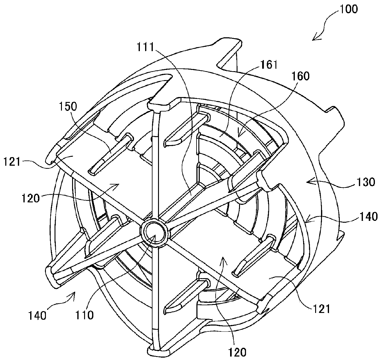
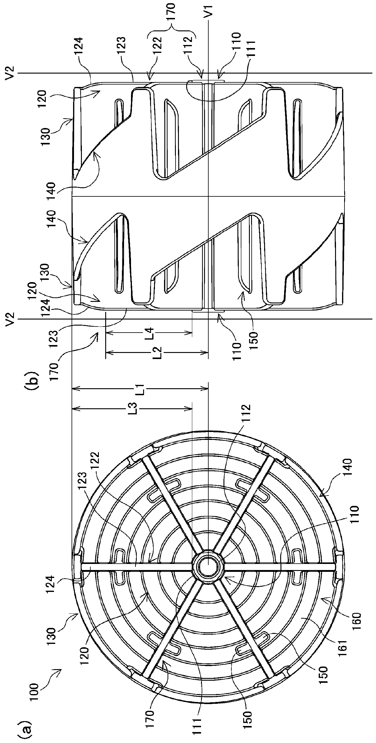
[0051] first, figure 1 with figure 2 The float 100 for lanes according to Embodiment 1 of the present application is shown. figure 1 It is an overall perspective view of the float 100 for the lane dividing line, figure 2 (a) is a front view of the float 100 for the lane line, figure 2 (b) is a side view of the float 100 for lane markings.

[0052] The lane-dividing float 100 has: a long cylindrical portion 110 located at the center of the lane-dividing float 100 through which the rope R can be inserted; The side surface 111 protrudes parallel to the rope R; and the wall surface 130 is connected to the side end 121 of the wing plate 120 and covers the wing plate 120 .

[0053] The wall surface 130 between adjacent blades 120 is formed obliquely. In addition, openings 140 are formed on both sides of the inclined portion, and waves advancing from the side enter into the lane line float 100 through the openings 140 . Furthermore, a protruding plate 150 parallel to the r...

Embodiment approach 2

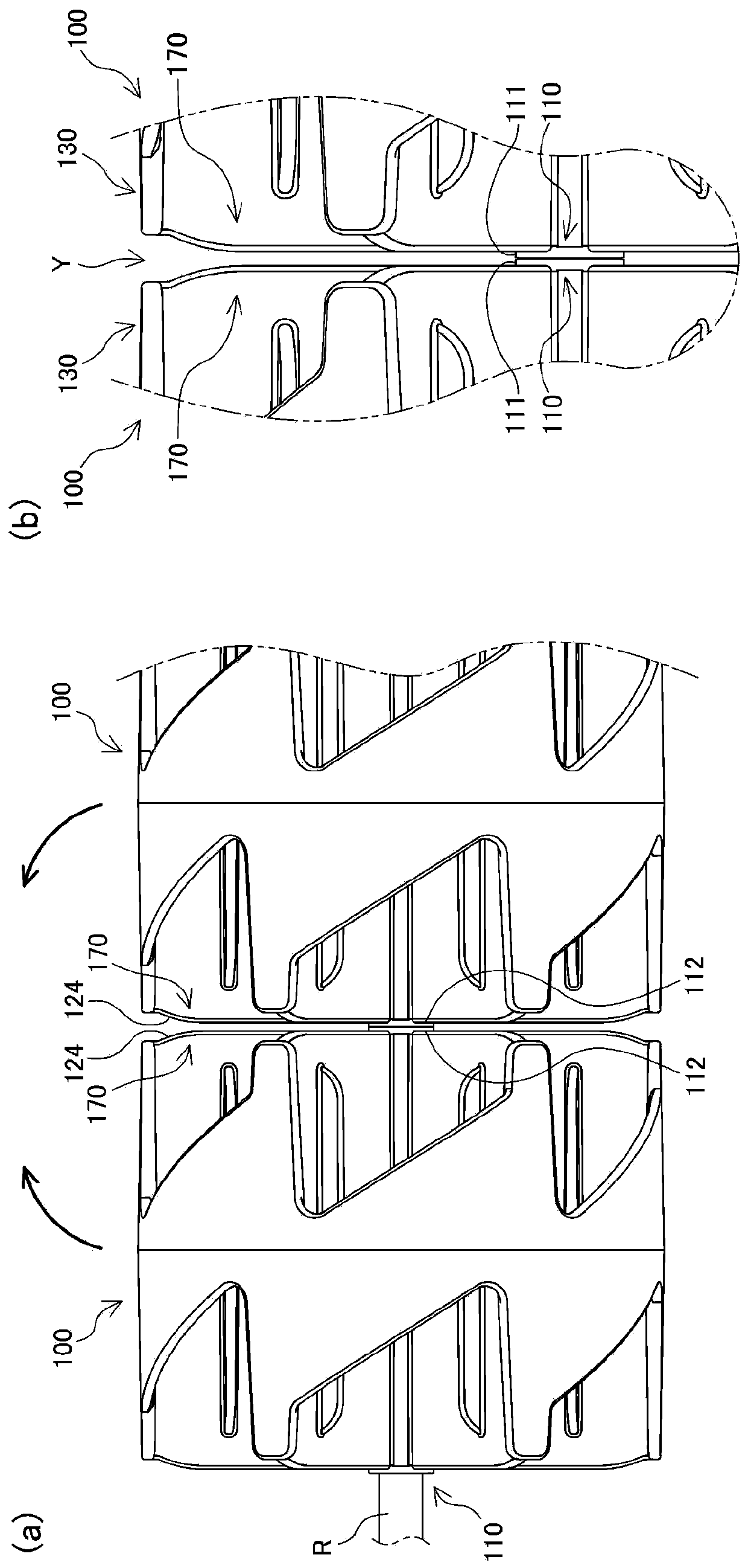
[0103] Next, refer to Figure 7 The lane-dividing float 100D according to Embodiment 2 of the present application will be described. It should be pointed out that Figure 7 (a) is a side view of the lane line float 100D, Figure 7 (b) is a side view of a state in which a plurality of lane-dividing floats 100D are attached to the rope R, Figure 7 (c) is to enlarge Figure 7 (b) is a side view of the vicinity of one outer end 170Da and the other outer end 170Db of the float 100D for lane dividing. In addition, the composition of the float 100D for lane-dividing lines is different from that of the float for lane-dividing lines except that the configuration of the one outer end 170Da and the other outer end 170Db is different from the outer end 170 of the float 100 for lane-dividing lines. 100 has the same configuration, so detailed description thereof will be omitted.

[0104] Such as Figure 7 As shown in (a), in one outer end portion 170Da of the float 100D for a lane li...


PUM


Abstract

Provided is a lane rope float having high wave absorbing performance as compared with a conventional lane rope float. A lane rope float 100 that is attached to a rope R via a tubular portion 110 and divides lanes of a pool, the lane rope float 100 comprising: a plurality of blades 120 that protrude from a side surface 111 of the tubular portion 110 in parallel with the rope R; and a wall surface portion 130 that is coupled to side end portions 121 of the blades 120 to cover the blades 120, wherein in an outer end portion 170 of the lane rope float 100 from the center of the tubular portion 110to the wall surface portion 130, at least 1 / 2 of the range from the center of the tubular portion 110 to the wall surface portion 130 is formed along a vertical plane V2 perpendicular to the tubularportion 110.

Description

technical field [0001] The present application relates to floats for lane lines installed in competition swimming pools and the like. Background technique [0002] In the past, various lane-marking floats are known, for example, such as Figure 8 As shown in (a) and (b), the float for lanes disclosed in Patent Document 1 is provided with a hollow inner float 1, a rope insertion hole 2 through which a rope R is inserted is formed at the center, and The left and right outer sides are formed as small-diameter stepped parts 4; and the outer float 6 has a boss 7 with a width smaller than that of the inner float 1, and a water inlet 9 is pierced on the central arm 8, and between the boss 7 and the rim 10 The fins 11 are formed, and the small-diameter inner surfaces 7a on the right and left of the boss of the outer float 6 are fitted into the small-diameter stepped portion 4 of the inner float 1 to combine them in a free-rotating shape. [0003] In addition, if Figure 8 As shown ...

Claims


Application Information

Patent Timeline
Patent Type & Authority Applications(China)
IPC IPC(8): A63K3/00E04H4/14
CPCE04H4/143
Inventor 林英俊小泽英郎
Owner GIFU PLAST IND CO LTD
Learn More