
Fan speed regulation method, device and storage medium of a display controller

A technology of display controller and speed regulation method, which is applied in the directions of pump control, machine/engine, cooling/ventilation/heating transformation, etc., which can solve the problems of fan speed increase, increased use risk, user loss, etc., and reduce fan speed. Effects of noise and dust, improvement of use efficiency and service life

Active Publication Date: 2021-08-17
SHENZHEN AOTO ELECTRONICS
View PDF6 Cites 0 Cited by
  • Summary
  • Abstract
  • Description
  • Claims
  • Application Information

AI Technical Summary

Problems solved by technology

The existing technology can only pre-set the conversion table from the temperature of the collection point to the fan speed based on the empirical value, or use the ambient temperature of a single or multiple devices as the temperature of the collection point, and after simple average calculation, the fan speed can be obtained, and Control the fan speed of the controller for the LED display
The existing technology cannot accurately divide the areas of each processor, nor can it individually control the speed of fans in each area, resulting in the inability to solve the problem of heat concentration caused by high local loads
If all the fans operate at the same time, it will cause waste of power resources and unnecessary dust and noise at the same time, which is very unfavorable for dust prevention and noise reduction. It also shortens the service life and maintenance cycle of fans and related equipment, and increases the risk of use. increased maintenance costs
In the case of failure of individual ambient temperature acquisition modules, the cooling system will be completely paralyzed, causing unnecessary losses to users
Based on the control of the average temperature of the multi-processors in the controller based on the display screen, the failure state caused by the abnormality of a single temperature collection point can be avoided. However, for large-scale equipment, the temperature rise of one collection point will cause the corresponding The speed of the fan is pulled up
However, areas with low local loads will still get higher fan speeds than they require, resulting in excess heat dissipation, which is detrimental to energy saving, noise reduction and dust prevention

Method used


Image

  • Fan speed regulation method, device and storage medium of a display controller
  • Fan speed regulation method, device and storage medium of a display controller
  • Fan speed regulation method, device and storage medium of a display controller

Examples


Embodiment approach

[0095] Please refer to Figure 10 , the second embodiment of the display screen controller provided by the present invention includes: a regional fan 900, a regional fan 902, a regional fan 906, a regional fan 914, a detection module 904, a setting module 908, an alarm module 910, and a computing module 912 , a regional processor 916 , a chip 918 , a central processing unit 920 , a speed control module 922 , a regional processor S916 , and a regional unit 924 .

[0096] Specifically, in this embodiment, the detection module 904 includes a working environment temperature detection unit and a working chip temperature detection unit, the working environment temperature detection unit is used to obtain the working environment temperature, and the working chip temperature The detection unit is used to obtain the working chip temperature;

[0097] The calculation module 912 includes a calculation unit and a judgment unit; the calculation unit is used to obtain the fan speed value F...


PUM


Abstract

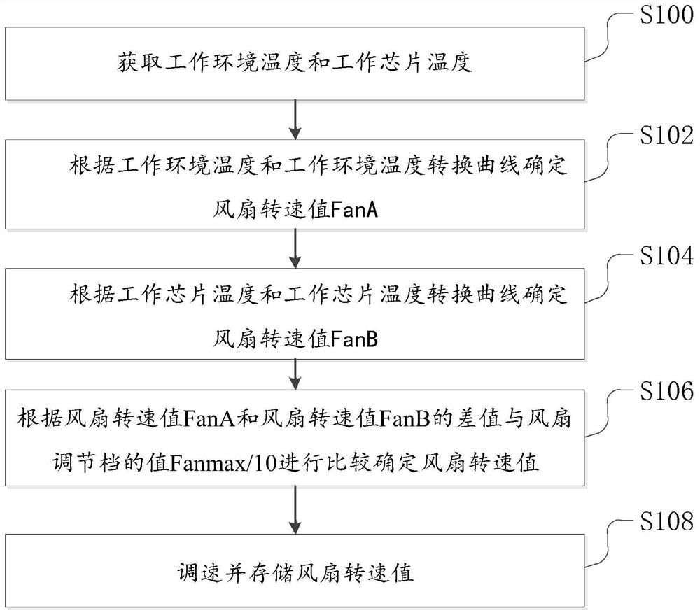
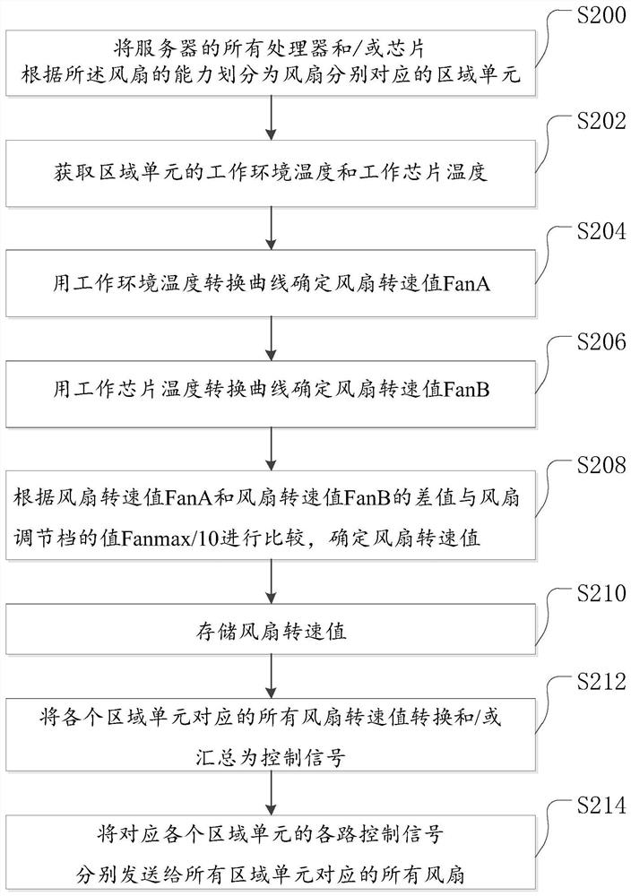
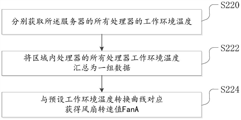
The present invention relates to a fan speed regulation method of a display controller, a device and a machine-readable storage medium, wherein the fan speed regulation method of a display controller includes: obtaining the temperature of the working environment and the temperature of the working chip; The fan speed value FanA is determined by the ambient temperature conversion curve; the fan speed value FanB is determined by the working chip temperature conversion curve; the fan speed is determined by comparing the difference between the fan speed value FanA and the fan speed value FanB with the fan adjustment gear value Fanmax / 10 value; adjust and store the fan speed value. The controller for the display screen is divided into areas, and the data of the working environment temperature and the working chip temperature are collected and calculated respectively, and the speed is controlled to improve the efficiency of the fan, improve the heat dissipation effect, improve the service life of various equipment in the controller, save energy, Reduce fan noise and dust.

Description

technical field [0001] The present invention relates to the field of controllers, in particular to a fan speed regulation method, device and machine-readable storage medium of a display screen controller. Background technique [0002] At present, the fan cooling system of the mainstream display screen controller usually uses the ambient temperature acquisition module to obtain the temperature of the acquisition point. In the prior art, the temperature of the collection point used for calculation is the ambient temperature of a single-use device, or the temperature of multiple processors in the device is collected and the average temperature of the processors is obtained through calculation. Through the training curve corresponding to the temperature of the collection point to the fan speed, or setting the conversion table of the temperature of the collection point corresponding to the fan speed according to the experience value, the fan speed of the controller for the displa...

Claims


Application Information

Patent Timeline
Patent Type & Authority Patents(China)
IPC IPC(8): F04D27/00H05K7/20
CPCF04D27/004H05K7/20136H05K7/20209
Inventor 颜春晓孙兴红吴振志吴涵渠
Owner SHENZHEN AOTO ELECTRONICS
Learn More