
Injection valve of multi-point injection engine added with mixer

A mixer and injection valve technology, which is applied in the direction of machine/engine, engine components, engine control, etc., can solve the problems of uneven mixing of mixed gas, large change of mixed gas concentration, and insufficient injection accuracy, so as to facilitate control and improve Effect of uniformity and accuracy improvement

Pending Publication Date: 2020-02-11
ANYANG INST OF TECH
View PDF0 Cites 0 Cited by
  • Summary
  • Abstract
  • Description
  • Claims
  • Application Information

AI Technical Summary

Problems solved by technology

[0003] Gas engines with multi-point injection, because the high-pressure gas forms a mixture with air in the intake manifold, and the structure of the intake manifold is generally short, there is often not enough space and time for the gas to fully mix with the air, which will cause the gas to enter the cylinder. The mixed gas mixture is unevenly mixed, which leads to poor combustion conditions in the cylinder and lower thermal efficiency; at the same time, due to the dynamic change of gas pressure, the injection accuracy is not enough, resulting in a large change in the concentration of the mixed gas, resulting in poor work done in the cylinder

Method used


Image

  • Injection valve of multi-point injection engine added with mixer
  • Injection valve of multi-point injection engine added with mixer
  • Injection valve of multi-point injection engine added with mixer

Examples


Embodiment Construction

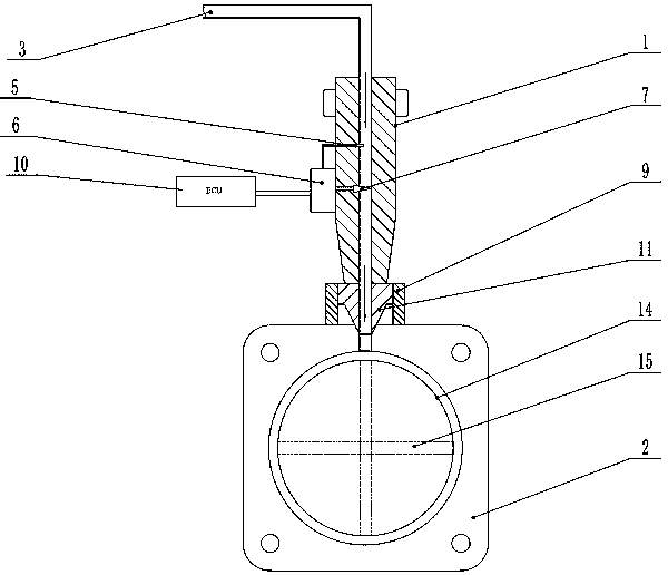
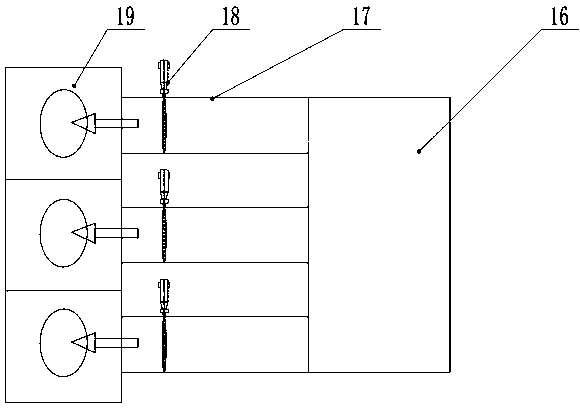
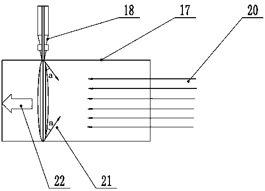
[0018] combine Figure 1~4 , an injection valve of a multi-point injection engine equipped with a mixer according to the present invention includes a multi-point injection valve body 1, a mixer 2, a gas pressure sensor 5, an injection valve controller 6, an injection valve needle 7, and a connecting valve seat 9. The mixer 2 is provided with a mixer conical sealing surface 11, the lower end of the multi-point injection valve body 1 is bonded and sealed with the mixer conical sealing surface 11, the mixer 2 is fixedly connected to the valve seat 9, and the valve seat 9 is connected to the valve The seat 9 fixes the lower end of the multi-point injection valve body 1, and the mixer 2 is provided with a mixer annular cavity 14 and a cross injection frame 15. The inner hole of the multi-point injection valve body 1 communicates with the mixer annular cavity 14 in the mixer 2, The inner side of the mixer annular chamber 14 is fixed with the cross end of the cross injection frame 15...


PUM


Abstract

The invention discloses an injection valve of a multi-point injection engine added with a mixer. The injection valve comprises a multi-point injection valve body and the mixer; the mixer is fixed at the lower end of the multi-point injection valve body; a mixer annular cavity and a cross injection frame are arranged in the mixer; an inner hole of the multi-point injection valve body communicates with the annular cavity of the mixer; a cross end part of the cross injection frame is fixed on the inner side of the annular cavity of the mixer; multiple first injection holes radially penetrating through the inner side are uniformly distributed on the inner side wall of the annular cavity of the mixer in the peripheral direction; the first injection holes are inclined towards an air intake direction of an intake manifold; the inner hole of the annular cavity of the mixer communicates with inner holes of two cross edges of the cross injection frame; the two cross edges are provided with multiple second injection holes uniformly distributed and penetrating in the directions of the cross edges of vertical holes; and air is firstly mixed with gas injected by the first injection holes once, and then, is mixed with gas injected by the second injection holes, so that the air and the gas are uniformly mixed in the mixer.

Description

technical field [0001] The invention relates to an injection valve of a multi-point injection engine equipped with a mixer, which belongs to the field of gas engines. Background technique [0002] Gas engines generally refer to engines that use natural gas as fuel, and have been widely used in daily social production. According to the way the mixture is formed, gas engines are generally divided into single-point injection engines and multi-point injection engines. The multi-point injection gas engine is a gas engine that injects natural gas with a pressure of 3bar~5bar into the intake manifold, forms a uniform mixture with the inflowing air, and then inhales it into the cylinder to ignite and perform work. Compared with traditional low-pressure gas engines, multi-point injection gas engines have the advantages of fast torque response, low exhaust temperature and reduced risk of gas engine flashback. [0003] Gas engines with multi-point injection, because the high-pressure...

Claims


Application Information

Patent Timeline
IPC IPC(8): F02M21/04F02M21/02F02D41/34F02D41/26F02M35/10
CPCF02D41/0027F02D41/26F02D41/345F02M21/0257F02M21/0263F02M21/0278F02M21/042F02M35/10006Y02T10/30
Inventor 唐丽萍吕掌权张瑜姬利娜刘近平亢凤林
Owner ANYANG INST OF TECH
Learn More