
Manual and automatic dual hot stamping machine

A dual-purpose hot stamping machine and automatic technology, applied in printing machines, rotary printing machines, printing, etc., can solve the problems of lack of horizontal hot stamping, unsatisfactory, unfavorable hot stamping work, etc., achieve good hot stamping effect and improve work efficiency Effect

Pending Publication Date: 2020-02-11
唐绪明
View PDF0 Cites 0 Cited by
  • Summary
  • Abstract
  • Description
  • Claims
  • Application Information

AI Technical Summary

Problems solved by technology

When it is necessary to perform hot stamping on softer materials, the softer materials are easier to be blown away due to their weight, which is not conducive to the hot stamping work
At the same time, most of the existing hot stamping machines also lack the device for horizontal hot stamping, which cannot meet higher requirements

Method used


Image

  • Manual and automatic dual hot stamping machine
  • Manual and automatic dual hot stamping machine
  • Manual and automatic dual hot stamping machine

Examples


Embodiment Construction

[0030] The present invention will be described in detail below in conjunction with the accompanying drawings and specific embodiments.

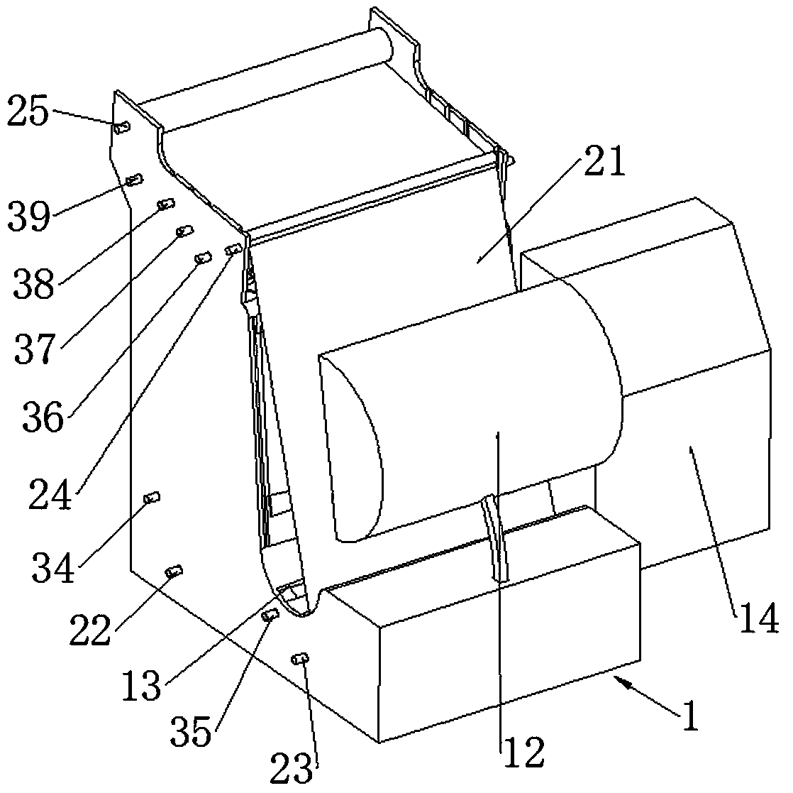
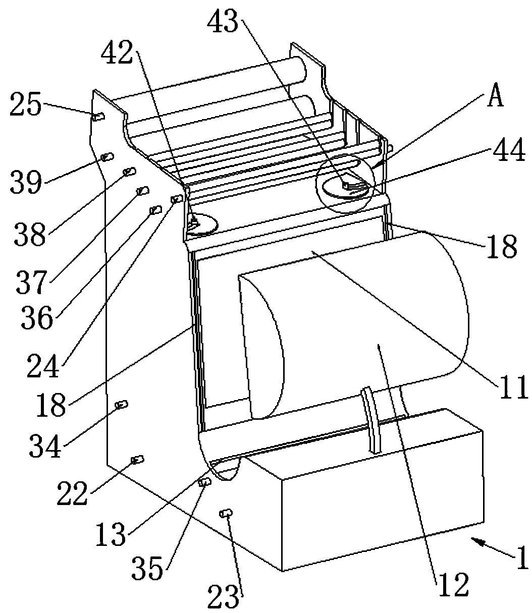
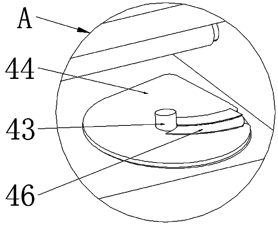
[0031] see Figure 1-12 , a manual and automatic dual-purpose hot stamping machine, including a body 1, a paper feeding mechanism 2, a longitudinal feeding mechanism 3 and an electric control cabinet 14; the body 1 is provided with a heating plate 11 and a pressure plate 12; the lower part of the body 1 is located A vertical through slot 13 is provided between the heating plate 11 and the pressure bearing plate 12; the paper feeding mechanism 2 includes a paper unwinding roller 22 that is rotatably fixed at the rear of the lower end of the machine body 1, and is rotatably fixed below the slot 13. The paper guide roller 23, the paper feed roller 24 fixed on the front part of the upper end of the machine body 1, and the paper take-up roller 25 fixed on the rear part of the upper end of the machine body 1 are rotated and fixed; one end of the co...


PUM


Abstract

The invention relates to a manual and automatic hot stamping machine which comprises a machine body, a paper feeding mechanism, a longitudinal feeding mechanism and an electric control cabinet. A cutgroove is formed in the lower portion of the machine body. The paper feeding mechanism comprises a paper unrolling roller, a paper guide roller, a paper feeding roller and a paper rolling roller. Oneend of a roll is wound around the paper unrolling roller, the middle portion of the roll penetrates the cut groove and is attached to the outer side of the paper guide roller and the outer side of thepaper feeding roller, and the other end of the roll is wound around the paper rolling roller. The longitudinal feeding mechanism comprises a longitudinal unrolling roller, an aluminum foil paper guide roller, multiple sets of longitudinal feeding rollers and a longitudinal rolling roller. one ends of multiple sets of longitudinal aluminum foil paper are wound on the longitudinal unrolling roller,the middle portions of the multiple sets of longitudinal aluminum foil paper penetrate the cut groove and can be attached to the outer side of the aluminum foil paper guide roller, and the other endsof the multiple sets of longitudinal aluminum foil paper are wound around the longitudinal rolling roller. The middle portions of the multiple sets of longitudinal aluminum foil paper are further attached to the outer sides of the different longitudinal feeding rollers. The roll is arranged on the outer side of the longitudinal aluminum foil paper, and multiple drive motors are in transmission connection with the paper feeding roller, the paper rolling roller, the multiple sets of longitudinal feeding roller and the longitudinal rolling roller correspondingly.

Description

technical field [0001] The invention relates to a manual and automatic dual-purpose hot stamping machine, which belongs to the technical field of hot stamping machinery. Background technique [0002] Bronzing process is a special printing process without ink. The so-called hot stamping refers to the process of hot stamping anodized aluminum foil onto the surface of the substrate under a certain temperature and pressure. During the bronzing process, the anodized aluminum is in contact with the hot stamping plate and the substrate through the action of pressure. Due to the heating of the electric heating plate, the hot stamping plate has a certain amount of heat, and the anodized aluminum is heated to melt the hot-melt dyeing resin layer and adhesive. The viscosity of the dyed resin layer decreases, but the viscosity of the special heat-sensitive adhesive increases after melting, and the aluminum layer and the anodized aluminum base film are peeled off and transferred to the ...

Claims


Application Information

Patent Timeline
Patent Type & Authority Applications(China)
IPC IPC(8): B41F19/06
CPCB41F19/062
Inventor 唐绪明
Owner 唐绪明
Learn More