PDC drill bit

A drill bit and bit body technology, applied in the direction of drill bits, drilling equipment, earthwork drilling and mining, etc., can solve the problems of thermal wear and cutting teeth can not be satisfied at the same time, to reduce adhesion, good auxiliary damage effect, increase concentration The effect of the spray effect

Pending Publication Date: 2020-02-07
BC P INC CHINA NAT PETROLEUM CORP +1
View PDF0 Cites 1 Cited by
  • Summary
  • Abstract
  • Description
  • Claims
  • Application Information

AI Technical Summary

Problems solved by technology

Conventional drill bits cannot meet the requirements of anti-balling in soft formations and avoiding thermal wear of cutting teeth in hard formations at the same time

Method used


Image

  • PDC drill bit
  • PDC drill bit
  • PDC drill bit

Examples


Embodiment Construction

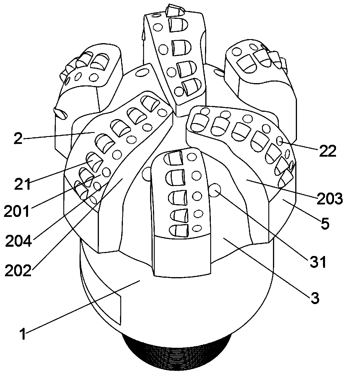
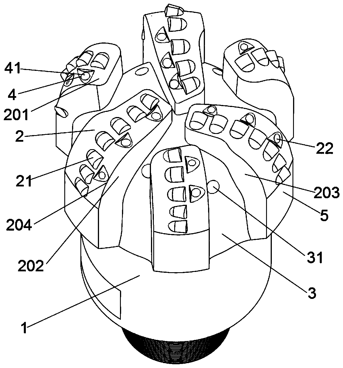
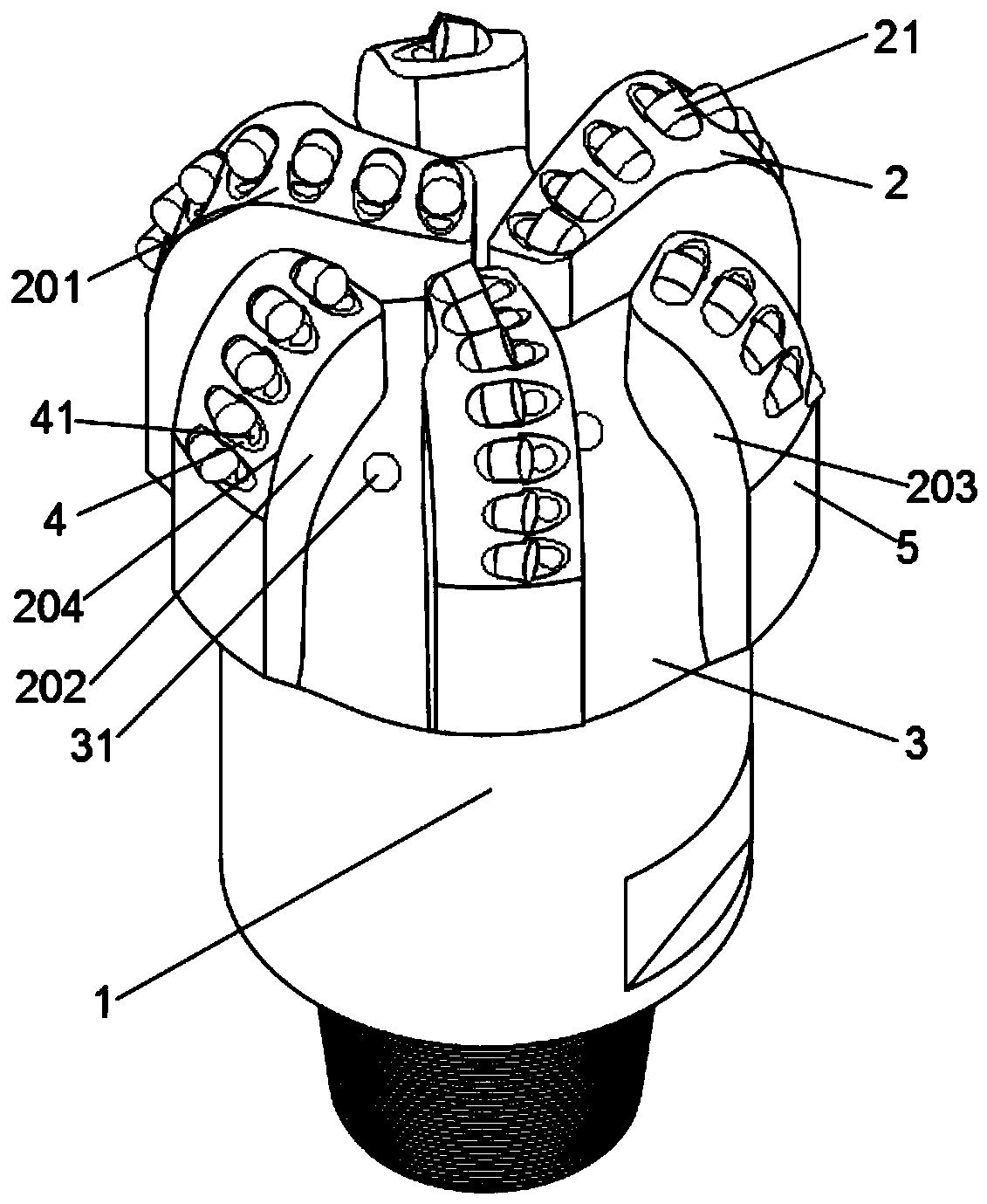
[0035] Such as figure 1 As shown, a PDC drill bit includes a drill body 1, several blades 2 extending from the drill body 1 or fixed on the drill body 1, the blades 2 are provided with cutting teeth 21, and the adjacent blades 2 Drilling fluid channel grooves 3 are formed between them; at least one blade 2 of the drill body 1 is provided with a water hole, and the outlet of at least one of the water holes is located between the leading edge 204 of the blade and the front row of cutting teeth.

[0036] Front row cutting teeth: In the direction of drill bit rotation, the front cutting teeth on the same blade are the front row cutting teeth, which are also the first teeth that the drill bit touches the rock for cutting during the working process.

[0037] Blade leading edge 204: Usually, for a blade, the intersection area between the blade tooth surface 201 of the blade 2 and the front side is called the blade leading edge 204, such as figure 1 shown. The cloth tooth surface 20...


PUM


Abstract

The invention relates to the technical field of a drill bit, in particular to a PDC drill bit. A device comprises a drill bit body and a plurality of blades extending from the drill bit body or fixedon the drill bit body, wherein cutting teeth are arranged on the blades, and drilling fluid flow channel grooves are formed between adjacent blades; a water hole is formed in at least one blade on thedrill bit body, and the outlet of the least one water hole is positioned between the front edge of the blade and the cutting teeth at the front row. According to the invention, the injection distanceof the water hole is obviously shortened, cuttings can be cleaned and transported timely, the cutting teeth can be sufficiently cooled timely to reduce the occurrence of thermal wear, and the PDC drill bit is suitable for soft, hard and hard alternating formations.

Description

Technical field: [0001] The invention relates to the technical field of drill bits, in particular to a PDC drill bit. Background technique: [0002] The drill bit is a rock-breaking tool used in drilling engineering to break rock and form a wellbore. In addition to the cutting structure, the hydraulic structure on the drill bit also plays an important role in the rock-breaking efficiency and service life of the drill bit, that is, cooling the cutting teeth, cleaning the bottom of the well, transporting cuttings, and assisting in rock breaking. At present, the design of the hydraulic structure on the drill bit is to arrange nozzles or water holes at different positions on the drill bit body, and the drilling fluid or cooling medium in the inner flow channel is sprayed out through the nozzles or water holes to clean and cool the cutting teeth. [0003] In the modern rapid drilling technology, the drill bit is required to have an excellent rock breaking and cutting structure, ...

Claims


Application Information

Patent Timeline
Patent Type & Authority Applications(China)
IPC IPC(8): E21B10/43E21B10/46E21B10/60
CPCE21B10/43E21B10/46E21B10/602
Inventor 于洪波杨迎新高清春宋东东任海涛张召峰余雷叶西安张昕冉
Owner BC P INC CHINA NAT PETROLEUM CORP
Why Eureka
Try Eureka