
Cooling fin double-gun plasma welding machine

A heat sink and plasma technology, applied in the field of ion welding machines, can solve the problems of high labor costs, low welding efficiency, and low welding precision

Inactive Publication Date: 2020-02-07
DONGGUAN YUANYI AUTOMATION EQUIP
View PDF0 Cites 1 Cited by
  • Summary
  • Abstract
  • Description
  • Claims
  • Application Information

AI Technical Summary

Problems solved by technology

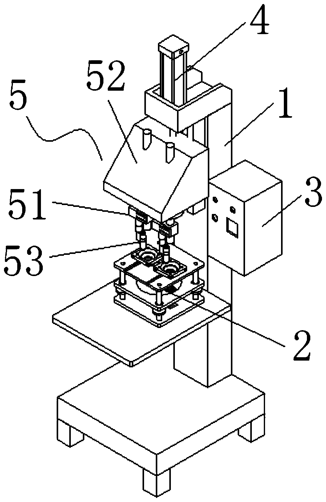
[0003] The technical problem to be solved by the present invention is to provide a plasma welding machine with double guns for heat sinks, which can realize the positioning of the stacked circular workpieces before welding through the mold mechanism, and can automatically position the circular workpieces stacked together through the double gun gear rotation mechanism. The middle round hole in the two stacked round workpieces is welded on the inner circle edge, so that the two round workpieces can be welded together after being welded through the inner circle edge of the middle round hole, and the welding process does not require manual labor. Participate in the operation, which has the advantages of high welding precision, high welding efficiency, good welding effect, high labor intensity of workers and high labor cost of the enterprise, which effectively solves the problem of low welding precision and low welding accuracy of traditional manual welding of heat sinks. The problems of low welding efficiency, poor welding effect, high labor intensity of workers and high labor cost of enterprises

Method used


Image

  • Cooling fin double-gun plasma welding machine
  • Cooling fin double-gun plasma welding machine
  • Cooling fin double-gun plasma welding machine

Examples


Embodiment Construction

[0021] In order to facilitate the understanding of the present invention, the present invention will be described more fully below with reference to the associated drawings. Preferred embodiments of the invention are shown in the accompanying drawings. However, the present invention can be embodied in many different forms and is not limited to the embodiments described herein. On the contrary, the purpose of providing these embodiments is to make the disclosure of the present invention more thorough and comprehensive.

[0022] Unless otherwise defined, all technical and scientific terms used herein have the same meaning as commonly understood by one of ordinary skill in the technical field of the invention.

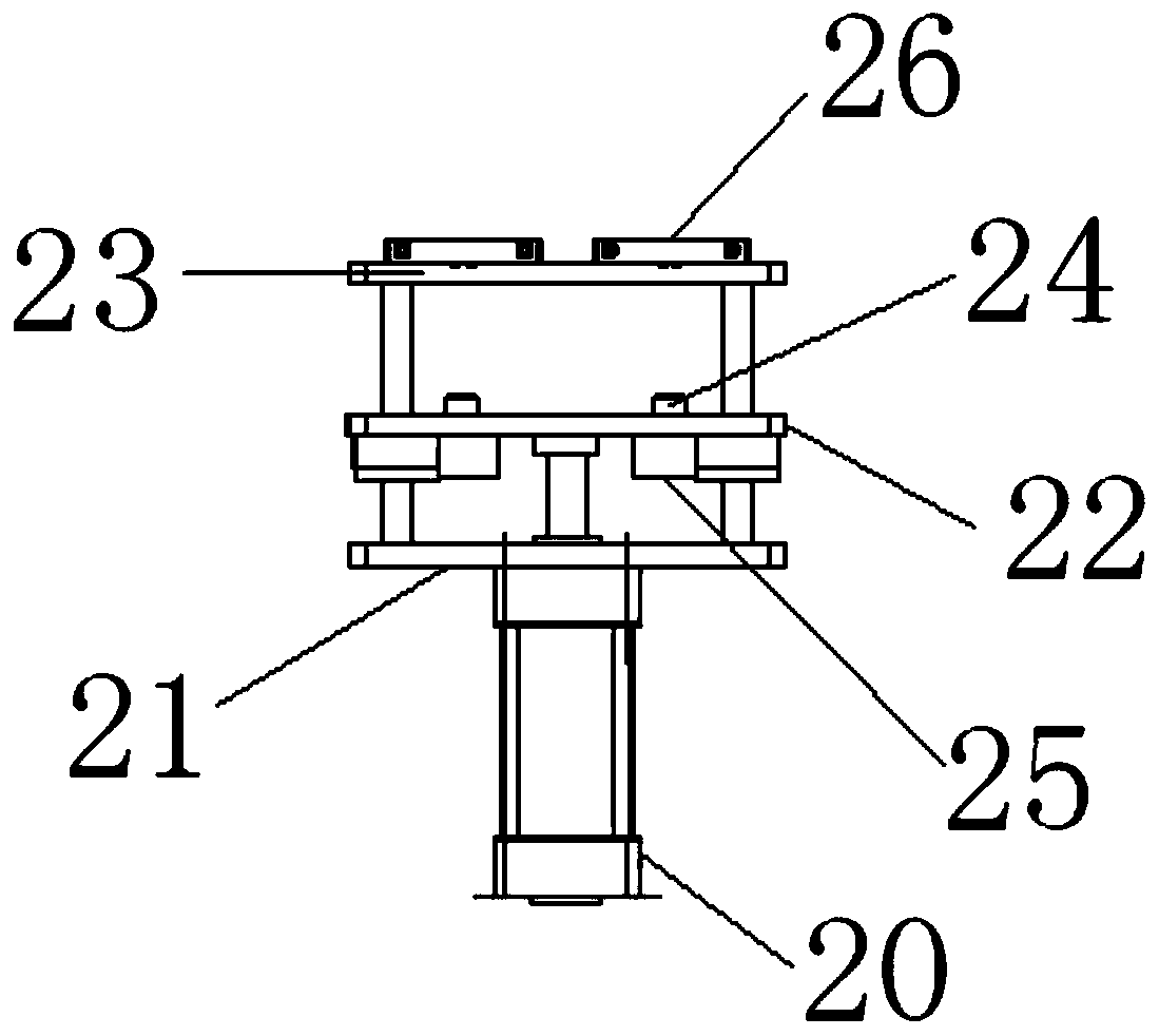
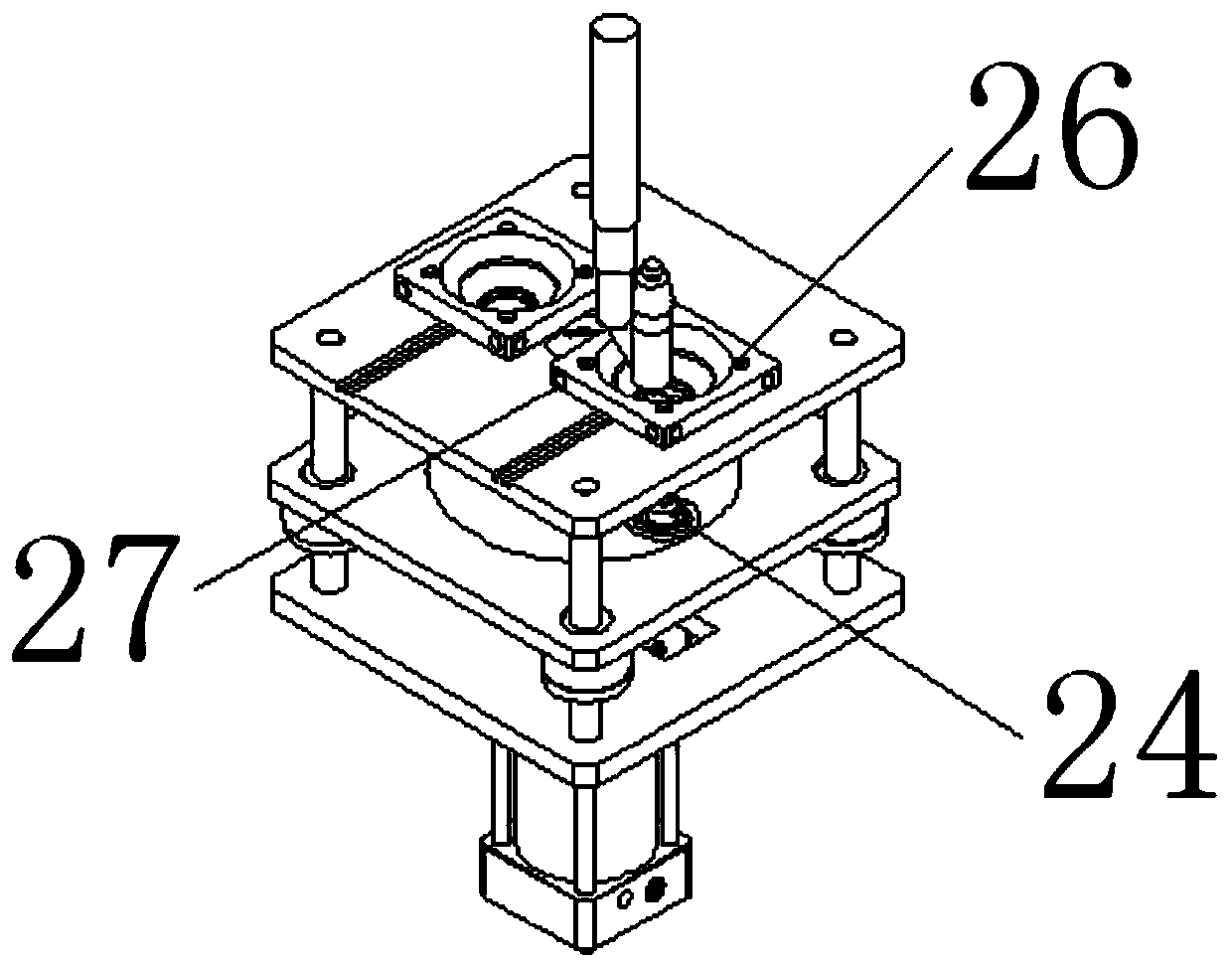
[0023] In this example, refer to Figure 1 to Figure 6 As shown, the heat sink double-gun plasma welding machine of the present invention includes a support 1, a mold mechanism 2 is provided on the front side of the support 1, a control box 3 is provided on the right si...


PUM


Abstract

The invention discloses a cooling fin double-gun plasma welding machine. The cooling fin double-gun plasma welding machine comprises a support. A mold mechanism is arranged on the front side of the support, a lifting cylinder is arranged on the front side of the upper end of the support, and a double-gun gear rotating mechanism is arranged at the bottom of the lifting cylinder. The mold mechanismcomprises a jacking cylinder, a base plate, a moving lower mold plate, a fixed upper mold plate, guide sleeves, lower locating copper columns, lower locating stretching cylinders, upper locating copper square blocks and cooling water connectors. By the adoption of the integral structural design, the purpose that the inner circle edge welding can be fully automatically conducted on middle circularholes in two circular workpieces which are stacked together is achieved, the purposes that the labor intensity of workers can be greatly reduced, the service cost of an enterprise can be reduced are achieved, and utilization is more convenient. Double plasma welding guns can achieve synchronous welding, are high in welding efficiency and conduct locating on the stacked circular workpieces throughthe arranged mold mechanism, and therefore the double-gun gear rotating mechanism can have the advantages of being high in welding accuracy and good in welding effect, and the cooling fin double-gun plasma welding machine meets the requirement of the enterprise for the large-scale batch production.

Description

technical field [0001] The invention relates to a plasma welding machine with double guns for heat sinks. Background technique [0002] The traditional welding of heat sinks is generally done by hand-held welding torches. The manual welding operation method not only has the problems of low welding accuracy, low welding efficiency and poor welding effect, but also has the labor force of workers. The strength and the high labor cost of the enterprise are insufficient, and it does not meet the requirements of large-scale and mass production of the enterprise. Later, some automatic welding machines appeared on the market, but their welding process requires the use of flux. The use of flux will cause certain harm to human health, and it does not meet the requirements of enterprise safety and environmental protection production. Contents of the invention [0003] The technical problem to be solved by the present invention is to provide a plasma welding machine with double guns ...

Claims


Application Information

Patent Timeline
Patent Type & Authority Applications(China)
IPC IPC(8): B23K10/02
CPCB23K10/02
Inventor 鲍颖张辉
Owner DONGGUAN YUANYI AUTOMATION EQUIP
Learn More