
Terminal cover for circuit breaker

A terminal cover and circuit breaker technology, which is applied in the field of terminal cover, can solve the problems of dismantling and observing, unable to quickly judge whether the circuit breaker terminal is faulty, and unable to quickly remove the terminal cover, etc., to achieve quick assembly and disassembly, simple structure Effect

Active Publication Date: 2020-02-04
MINJIANG UNIV
View PDF3 Cites 0 Cited by
  • Summary
  • Abstract
  • Description
  • Claims
  • Application Information

AI Technical Summary

Problems solved by technology

[0002] Circuit breaker terminals are also called switch terminals. Switch terminals are professionally used for various small circuit breakers, leakage circuit breakers, air switches, etc., and are used in complete sets of electronically controlled power distribution equipment and combined terminal electrical boxes. It is designed for the multi-way connection of the outlet end of the miniature circuit breaker or leakage circuit breaker at present. The multi-way connection of the outlet end of the circuit breaker can be realized through the circuit breaker terminal. In order to protect the normal service life of the circuit breaker terminal and prevent electric shock, so It is necessary to install a terminal cover on the surface of the circuit breaker terminal. Most of the existing terminal covers are fixed to the terminals by bolts. When the wiring of the circuit breaker terminal fails, the terminal cover cannot be removed quickly to observe the wiring of the terminals inside the terminal cover. , so that it is impossible to quickly judge whether the circuit breaker terminal is faulty

Method used


Image

  • Terminal cover for circuit breaker
  • Terminal cover for circuit breaker
  • Terminal cover for circuit breaker

Examples


Embodiment Construction

[0021] The present invention will be described in further detail below in conjunction with the accompanying drawings and specific embodiments.

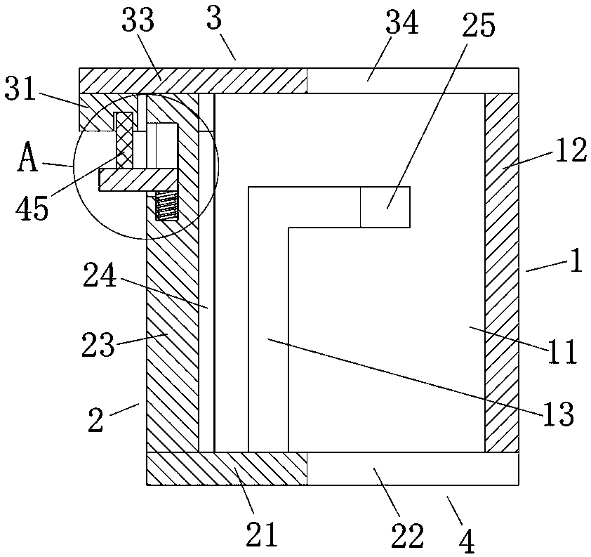
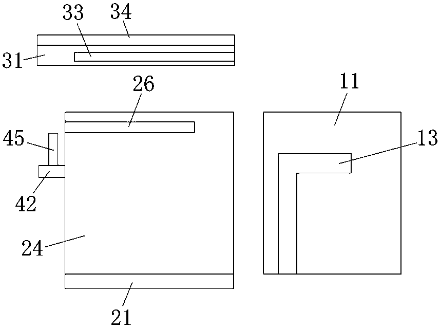
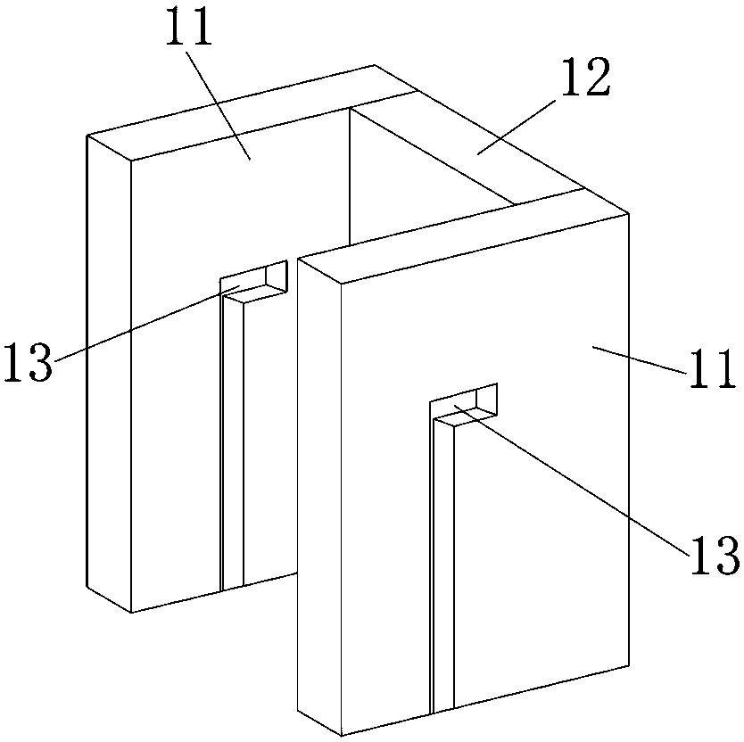
[0022] Such as Figure 1~6 As shown, a terminal cover for a circuit breaker of the present invention includes a terminal cover body 4 with an opening at the upper end and a push-pull upper cover 3 set on the upper end of the terminal cover body 4 , the upper ends of the front and rear sides of the terminal cover body 4 are Both are provided with horizontal card slots 26, and the left end of the terminal cover body 4 is provided with a fixed insertion rod 45 that can be lifted; Bar 32, the bottom surface of the left end of the push-pull upper cover 3 is provided with a limit slot 46 to facilitate the upward insertion of the fixed insertion rod 45 . The sliding fit of the horizontal clamping strip and the horizontal clamping groove can prevent the entire terminal cover from being separated up and down, and then insert the fixing rod in...


PUM


Abstract

The present invention relates to a terminal cover for a circuit breaker, which comprises a terminal cover body with an opening at the upper end and a push-pull upper cover covered on the upper end ofthe terminal cover body. The upper ends of the front and rear sides of the terminal cover body are provided with transverse clamping grooves; the left end of the terminal cover body is provided with aliftable fixed inserted rod; The lower parts of the front and rear ends of the push-pull upper cover are respectively provided with transverse clamping strips which are slidably engaged with the transverse clamping grooves; and the left bottom surface of the push-pull upper cover is provided with a limit slot which is convenient for upward insertion of the fixed inserted rod. The invention is simple and reasonable in structure and can be assembled and disassembled quickly; it is convenient to observe the wiring conditions of the terminals in the terminal cover; and then it can be quickly judged whether the circuit breaker terminal is faulty or not.

Description

Technical field: [0001] The invention relates to a terminal cover for a circuit breaker. Background technique: [0002] Circuit breaker terminals are also called switch terminals. Switch terminals are professionally used for various small circuit breakers, leakage circuit breakers, air switches, etc., and are used in complete sets of electronically controlled power distribution equipment and combined terminal electrical boxes. It is designed for the multi-way connection of the outlet end of the miniature circuit breaker or leakage circuit breaker at present. The multi-way connection of the outlet end of the circuit breaker can be realized through the circuit breaker terminal. In order to protect the normal service life of the circuit breaker terminal and prevent electric shock, so It is necessary to install a terminal cover on the surface of the circuit breaker terminal. Most of the existing terminal covers are fixed to the terminals by bolts. When the wiring of the circuit ...

Claims


Application Information

Patent Timeline
IPC IPC(8): H01H71/08H01H71/02
CPCH01H71/02H01H71/08
Inventor 谭巧林火养贺德华
Owner MINJIANG UNIV
Learn More