Temperature control method of heating tank of optical fiber fusion splicer

A temperature control method and technology of optical fiber fusion splicer, applied in the coupling of optical waveguides, light guides, optics, etc., can solve problems such as long-term worker health threats, high power density, and reduced welding strength, and achieve optimal furnace temperature control. , Excellent thermal effect control, and the effect of improving the quality of heat shrinkage

Active Publication Date: 2020-06-19
XIAN GUANGGU COMM TECH
View PDF11 Cites 0 Cited by
  • Summary
  • Abstract
  • Description
  • Claims
  • Application Information

AI Technical Summary

Problems solved by technology

The former needs to be bonded with high-temperature-resistant (above 250°C) adhesives. There are few domestic manufacturers producing such high-temperature adhesives. Although the PI heating film can be made into a flexible shape to improve heat conduction efficiency, the finished product has a high power density. It cannot be heated in a large area, and can only increase the temperature of a small local area, and extend to both sides through heat transfer; and it uses an aluminum-based heat conduction sheet, which will generate aluminum ions at high temperatures, posing a threat to the health of long-term workers
For the latter, the steel-based material itself has high temperature resistance, high thermal conductivity and mechanical strength, is not easy to deform, and is lower in cost than aluminum, so it is the preferred material; The heating speed is very fast, generally 7-10s can reach above 200°C, if the temperature control is not good, under a certain number of high-temperature thermal shocks (continuously heating above 300°C in the experiment, the solder joints will start to crack in about 30 minutes Phenomenon) The silver paste on the solder joint will fuse with the solder and peel off, resulting in the failure of the heating tank, and the cause of solder joint detachment mainly depends on the temperature on the pad, the higher the temperature, the faster the peeling speed; there are solder joints at both ends of the heating tank Under frequent high-temperature thermal shocks, the welding strength of the disc is reduced, or even detached to cause failure; therefore, it is necessary to reasonably control the upper temperature limit of the heating tank and the holding time, so that the heat-shrinkable sleeve can be quickly heat-shrinked and strengthened, and the above-mentioned problems can be avoided. question
[0003] Secondly, the voltage value at both ends of the resistor on the heating tank also affects the heating efficiency. The higher the power supply voltage is, the faster the heating rate will be. However, the fusion splicer uses a lithium battery for power supply. As the number of operations increases, the voltage will gradually decrease. This factor will also affect the heating tank. temperature rise time
Since the main control unit of the fusion splicer cannot predict the actual temperature of the heating tank, it is unreasonable to use the preset heating time parameters as the shutdown signal

Method used


Image

  • Temperature control method of heating tank of optical fiber fusion splicer
  • Temperature control method of heating tank of optical fiber fusion splicer
  • Temperature control method of heating tank of optical fiber fusion splicer

Examples


Embodiment Construction

[0037] The technical solutions in the embodiments of the present invention will be clearly and completely described below in conjunction with the embodiments of the present invention. Apparently, the described embodiments are only some of the embodiments of the present invention, not all of them. Based on the embodiments of the present invention, all other embodiments obtained by persons of ordinary skill in the art without making creative efforts belong to the protection scope of the present invention.

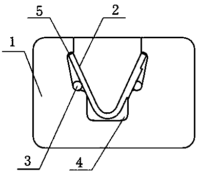
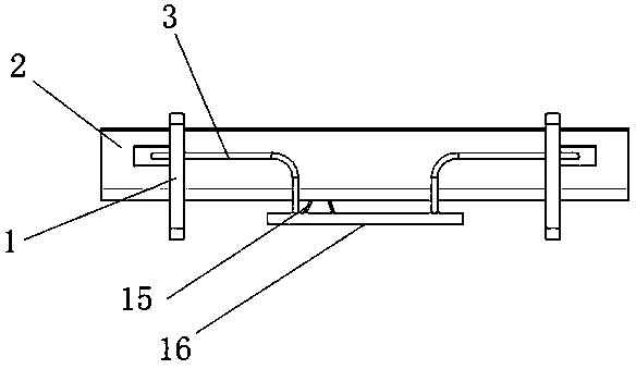
[0038] In an embodiment of the present invention, a structure of a heating tank of an optical fiber fusion splicer, such as Figure 1-2 As shown, a V-shaped heating tank 2 is included. The heating tank 2 is arranged in the U-shaped groove 4 inside the fixed support 1. The upper part of the side wall of the U-shaped groove 4 is provided with a card groove 5 extending outward from the groove. The heating groove 2 The end of the heating tank is clamped tightly in the slot 5, and...


PUM


Abstract

The present invention discloses a heating tank of an optical fiber fusion splicer and a temperature control method thereof. A V-shaped heating tank is arranged in a U-shaped groove inside a fixing support; the upper part of the side wall of the U-shaped groove is provided with a clamping groove extending outside the groove; the end of the heating tank is clamped in the clamping groove; two outer sides of the heating tank are provided with heating resistors with segmentedly distributed resistances; a heat-shrinkable sleeve contacts with the inner wall of the heating tank; a temperature sensor is connected with a main control unit through a temperature acquisition circuit; and the main control unit is connected with leads at both ends of the heating resistors through a PWM heating control circuit. The temperature of the heating tank of the invention increases gradually from both ends to the center; the temperature difference between the wall of the heating tank and the temperature in thetank is reduced; the utilization value of the heating value is improved; through the PWM heating control circuit and the temperature acquisition circuit, the linearization of the heating curve is ensured; the heat shrinkage quality of the heat-shrinkable sleeve is improved; the electric energy consumption is effectively reduced; the working efficiency of a heating furnace is improved; and the service life is prolonged.

Description

technical field [0001] The invention belongs to the technical field of optical fiber fusion splicers, and relates to a method for controlling the temperature of a heating tank of an optical fiber fusion splicer. Background technique [0002] After the optical fiber connector is fused and spliced, the fusion point needs to be protected. Generally, heat-shrinkable sleeves of corresponding specifications are used for different fiber types. Put a heat-shrinkable sleeve on the optical fiber joint, and put it into the heating device for heat-shrinkage fastening. There are two processes: one is the heating process, and the other is the cooling or heat preservation process. The heating rate is mainly determined by the manufacturer's heating tank material (usually resistive material) and the voltage applied to both ends of the material. There are two main types of heating tank structures for optical fiber fusion splicers of existing manufacturers: one is aluminum substrate wrapped...

Claims


Application Information

Patent Timeline
Patent Type & Authority Patents(China)
IPC IPC(8): G02B6/255
CPCG02B6/2551G02B6/2553
Inventor 李向阳郭杰王迎利关文键
Owner XIAN GUANGGU COMM TECH
Why Eureka
Try Eureka