
Electronic injection pen

An injection pen and electronic technology, applied in the field of medical supplies, can solve the problems of low precision, easy to puncture the skin by mistake, and inability to inject according to the curve (such as slow first, etc.), to achieve a reasonable structure layout and the effect of being easy to hold

Pending Publication Date: 2020-02-04
杭州快通科技有限公司
View PDF6 Cites 2 Cited by
  • Summary
  • Abstract
  • Description
  • Claims
  • Application Information

AI Technical Summary

Problems solved by technology

[0002] The current electronic injection pen generally has only one DC motor, which usually has the following problems: before the injection, the needle needs to be manually inserted into the skin, causing great psychological pressure to the patient; because the same motor is used for exhaust and injection, The exhaust speed is consistent with the injection speed, and it takes a few minutes to complete one exhaust; manual operation is required to install and pull out the needle, and it is easy to accidentally pierce the skin during the insertion and extraction process; when injecting, the injection speed is constant and cannot be injected according to the curve (such as slow injection first, then constant speed injection, etc.); the precision is not high, because the DC motor is used, the speed is greatly disturbed by factors such as voltage
For injection pens with dual motors, there is usually a connection between the two driving motors, or the location layout is unreasonable, which is not conducive to popularization and use.

Method used


Image

  • Electronic injection pen
  • Electronic injection pen
  • Electronic injection pen

Examples


Embodiment 1

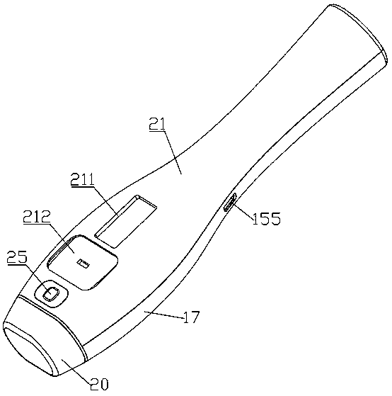
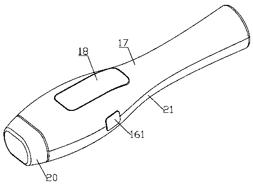
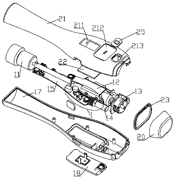
[0062] An electronic injection pen, such as Figure 1 to Figure 17 , including a pen case, a first driving mechanism 11, a liquid medicine cartridge assembly 12, a needle changing mechanism 13, a second driving mechanism 14, a sensing control unit 15, a bottle changing switch assembly 16, a display unit 22 and a battery unit 24, each mechanism , components and units are all installed in the inner cavity of the pen case, the needle exchange mechanism 13 is at the front end of the injection pen, the liquid medicine cartridge assembly 12 is at the rear side of the needle exchange mechanism 13, and the first driving mechanism 11 is at the side of the liquid medicine cartridge assembly 12 On the rear side, the battery unit 24 is located on the rear side of the first drive mechanism 11 and at the rear end of the electronic injection pen, the sensor control unit 15 is connected to the first drive mechanism 11, the second drive mechanism 14, the battery unit 24 and the display unit 22,...

Embodiment 2

[0121] In this embodiment, an electronic injection pen is provided. The first driving mechanism 11 of the electronic injection pen can adopt a linear motor or an electronic push rod, etc., and can adopt a method in which a non-exposed rotating screw rod cooperates with a linearly running screw sleeve. However, a linear stepping motor is used, that is, the exposed output shaft itself can move in a straight line, etc., as long as it can realize switching of at least two speeds.

[0122] For example, the first drive mechanism 11 includes a first motor, a screw and a threaded sleeve (nut), the output shaft of the first motor is connected to the threaded sleeve, the threaded sleeve has internal threads, and the screw is threaded on the threaded sleeve, the first motor As a stepping motor, a guide mechanism (such as a guide block or a guide groove) can be set to guide the screw so that the screw can move linearly under the action of the threaded sleeve. Other shapes, structures, and...

Embodiment 3

[0124] In this embodiment, an electronic injection pen is provided, see Figure 20 with Figure 21 , its second drive mechanism 14 includes a second motor 141, a lead screw 144 and a nut one 145, and the second motor 141 is a DC motor. The output shaft of the second motor is connected to the lead screw 144, and the lead screw 144 is screwed on the nut one 145. Specifically, the external thread on the lead screw 144 is screwed on the internal thread on the nut one 145, and the nut one 145 is fixedly mounted on the medicine On the support three 126 on the liquid cylinder assembly. One end of the nut one 145 fixed on the bracket three 126 has a protrusion, and the bracket three 126 is provided with a through hole at the fixing part for the protrusion to be engaged and fixed. A sensor triggering portion for triggering the sensors 2 and 3 protrudes from the bracket 3 126 .

[0125] The liquid medicine cartridge assembly includes a liquid medicine cartridge, a guide rod, a bracke...


PUM


Abstract

The invention discloses an electronic injection pen. The electronic injection pen comprises a pen shell, a first driving mechanism, a medicinal liquid cylinder assembly, a needle changing mechanism, asecond driving mechanism, a sensing control unit, a bottle changing switch assembly and a battery unit, wherein the various mechanisms, assemblies and units are mounted in an inner cavity of the penshell; the needle changing mechanism is positioned at the front end of the pen shell; the medicinal liquid cylinder assembly is positioned on the rear side of the needle changing mechanism; the firstdriving mechanism is positioned on the rear side of the medicinal liquid cylinder assembly; the sensing control unit is connected with the first driving mechanism, the second driving mechanism and thebattery unit; the battery unit supplies power to the sensing control unit, the first driving mechanism and the second driving mechanism; the first driving mechanism can act on a piston of a card-typebottle arranged in the medicinal liquid cylinder assembly; and the second driving mechanism is connected with the medicinal liquid cylinder assembly so as to drive the medicinal liquid cylinder assembly to be moved frontwards and backwards. The electronic injection pen disclosed by the invention has the advantages that double driving mechanisms are adopted and separately operate, and mutual influence cannot be produced. The sensing control unit can control coordination of the various parts, and therefore, the electronic injection pen is intelligent and convenient.

Description

technical field [0001] The invention relates to the technical field of medical supplies, and belongs to syringes, in particular to an electronic injection pen. Background technique [0002] The current electronic injection pen generally has only one DC motor, which usually has the following problems: before the injection, the needle needs to be manually inserted into the skin, causing great psychological pressure to the patient; because the same motor is used for exhaust and injection, The exhaust speed is consistent with the injection speed, and it takes a few minutes to complete one exhaust; manual operation is required to install and pull out the needle, and it is easy to accidentally pierce the skin during the insertion and extraction process; when injecting, the injection speed is constant and cannot be injected according to the curve (such as slow injection first, then constant speed injection, etc.); the precision is not high, because the DC motor is used, the speed i...

Claims


Application Information

Patent Timeline
IPC IPC(8): A61M5/20A61M5/24
CPCA61M5/2422A61M5/20A61M2005/206A61M2005/2437
Inventor 董大銮金超
Owner 杭州快通科技有限公司
Learn More