
Convenient-to-adjust constant-temperature and constant-humidity power distribution cabinet

A constant temperature and humidity, power distribution cabinet technology, applied in substation/distribution device housing, electrical components, substation/switch layout details, etc., can solve the problems of accelerated air flow, inconvenient use, poor flexibility, etc. , easy to adjust, speed up the effect of air flow

Active Publication Date: 2020-01-31
深圳市威银电气技术有限公司
View PDF8 Cites 12 Cited by
  • Summary
  • Abstract
  • Description
  • Claims
  • Application Information

AI Technical Summary

Problems solved by technology

[0003] In the patent No. CN106159742B, a structure of a constant temperature and humidity power distribution cabinet is disclosed. The structure is driven by a stepping motor. etc. to realize the adjustment of temperature and humidity inside the power distribution cabinet; but the structure also has the following defects: 1. The power distribution cabinet is fixed, which is inconvenient to adjust its height and inconvenient to move horizontally, resulting in its flexibility Poor performance, inconvenient to use, and not strong in practicability; 2. In the process of adjusting the temperature of the power distribution cabinet, the top cover cannot be lifted so that the cabinet is not a closed space, and the air flow is accelerated to further dissipate heat

Method used


Image

  • Convenient-to-adjust constant-temperature and constant-humidity power distribution cabinet
  • Convenient-to-adjust constant-temperature and constant-humidity power distribution cabinet
  • Convenient-to-adjust constant-temperature and constant-humidity power distribution cabinet

Examples


Embodiment Construction

[0039]The following will clearly and completely describe the technical solutions in the embodiments of the present invention with reference to the accompanying drawings in the embodiments of the present invention. Obviously, the described embodiments are only some, not all, embodiments of the present invention. Based on the embodiments of the present invention, all other embodiments obtained by persons of ordinary skill in the art without creative efforts fall within the protection scope of the present invention.

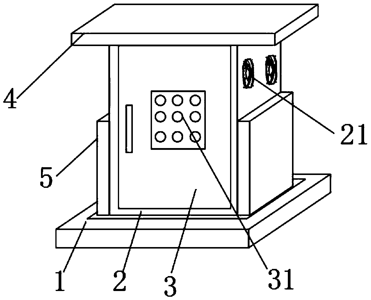
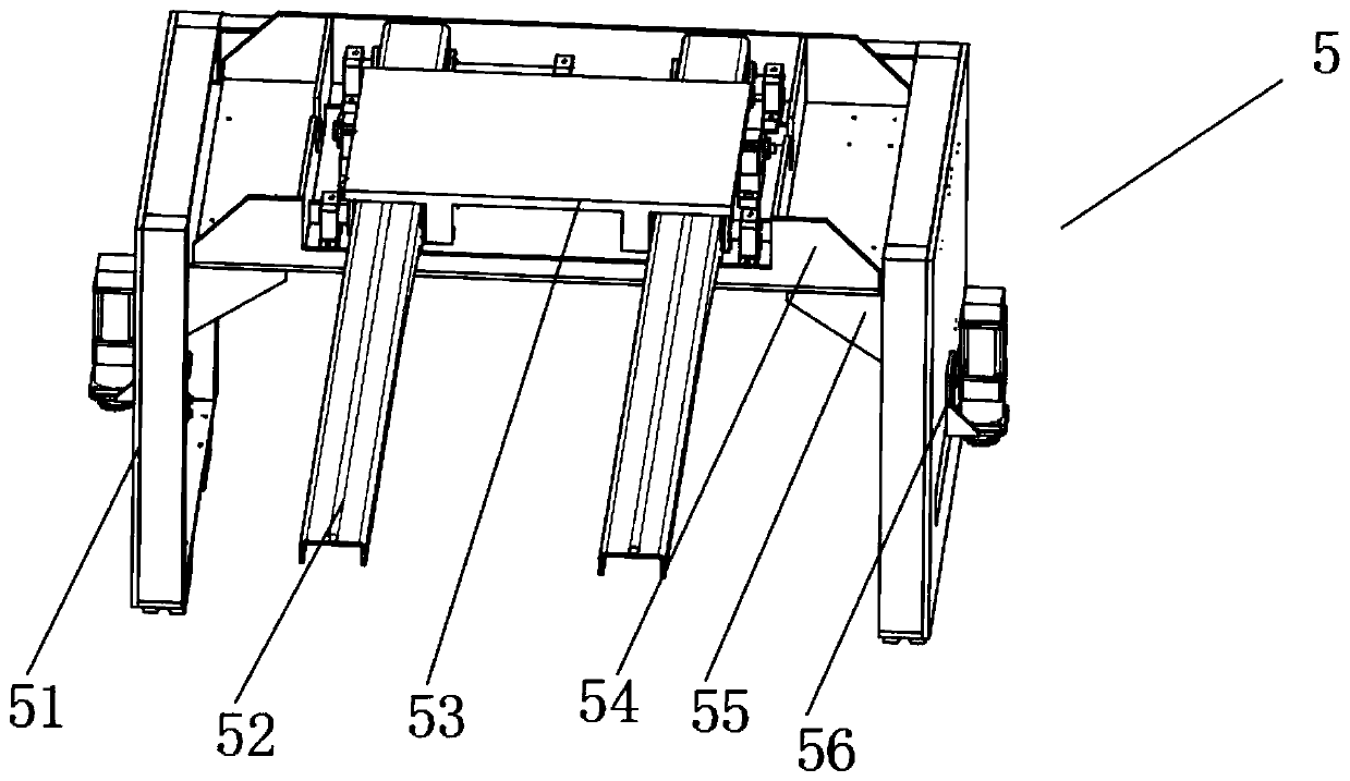
[0040] see Figure 1-6 As shown, an easy-to-adjust constant temperature and humidity power distribution cabinet includes a base 1, a cabinet body 2, a top cover 4, and an adjustment mechanism 5. The inside of the base 1 is provided with an adjustment mechanism 5, and the adjustment mechanism 5 is provided with There is a cabinet body 2, and a top cover 4 is arranged on the cabinet body 2;

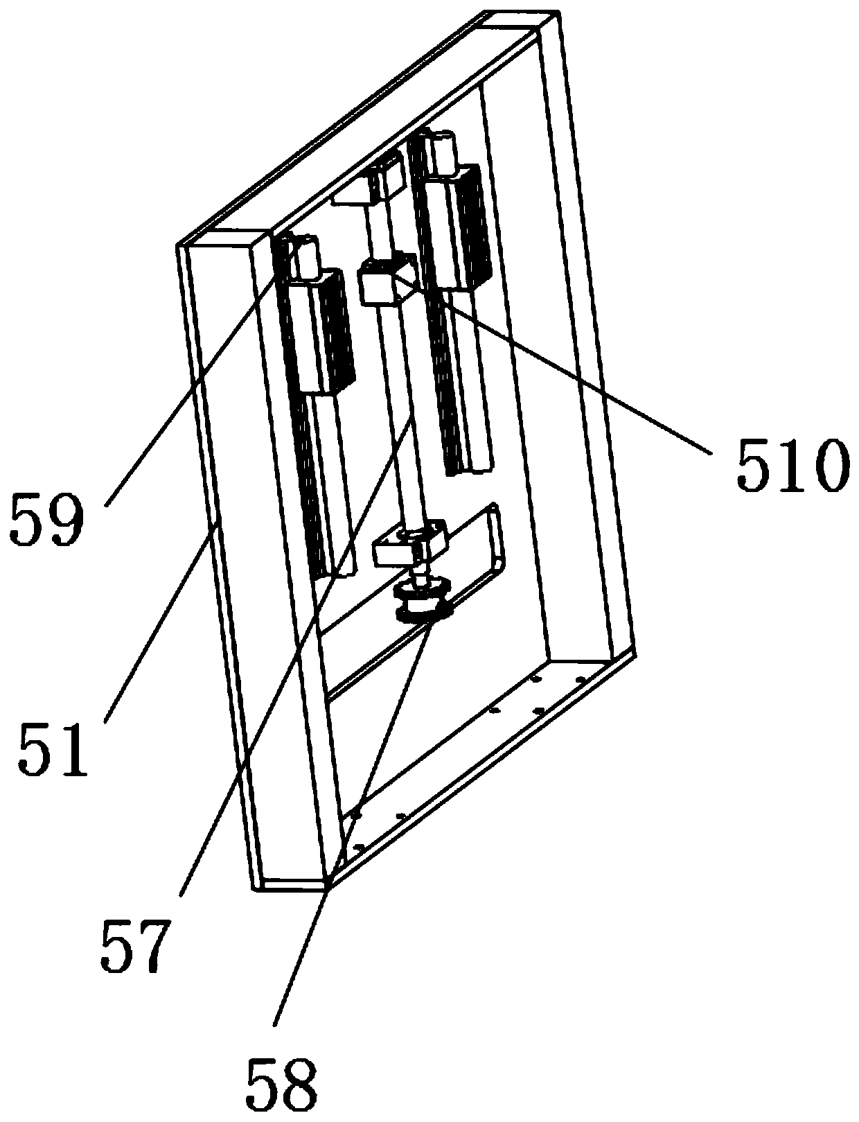
[0041] The adjustment mechanism 5 includes a fixed seat 51, a slide rail 52...


PUM


Abstract

The invention discloses a convenient-to-adjust constant-temperature and constant-humidity power distribution cabinet. The power distribution cabinet comprises a base, a cabinet body, a top cover and an adjusting mechanism, wherein the adjusting mechanism is arranged in the base, the cabinet body is arranged on the adjusting mechanism, the top cover is arranged on the cabinet body, the adjusting mechanism comprises a fixing base, a sliding rail, a sliding plate, a supporting plate, a wedge block, a first servo motor, a first lead screw, a driven wheel, a guide rod, a first sliding block, a driving wheel, a first gear, a second sliding block, a first rack and a second servo motor. The power distribution cabinet is advantaged in that through the adjusting mechanism, the height of the cabinetbody is conveniently adjusted, moreover, the cabinet body can be driven to move in the horizontal direction, and adjustment and use are convenient; through a sensor, a controller and the rack jackingtop cover, the cabinet body is not a closed space, air flow is accelerated, and heat dissipation and dehumidification are carried out.

Description

technical field [0001] The invention relates to the technical field of power distribution cabinets, in particular to a constant temperature and humidity power distribution cabinet that is easy to adjust. Background technique [0002] The power distribution cabinet (box) is divided into power distribution cabinet (box), lighting distribution cabinet (box), metering cabinet (box), and is the final equipment of the power distribution system. The power distribution cabinet is a general term for the motor control center. The power distribution cabinet is used in the occasions where the load is relatively scattered and there are few circuits; the motor control center is used in the occasions where the load is concentrated and there are many circuits. They distribute the electric energy of a certain circuit of the upper-level power distribution equipment to the nearest load. This level of equipment shall provide protection, monitoring and control of the load. [0003] In the pat...

Claims


Application Information

Patent Timeline
IPC IPC(8): H02B1/30H02B1/52H02B1/56H02B1/28
CPCH02B1/28H02B1/30H02B1/303H02B1/306H02B1/52H02B1/565
Inventor 周佳斌詹建朝
Owner 深圳市威银电气技术有限公司
Learn More