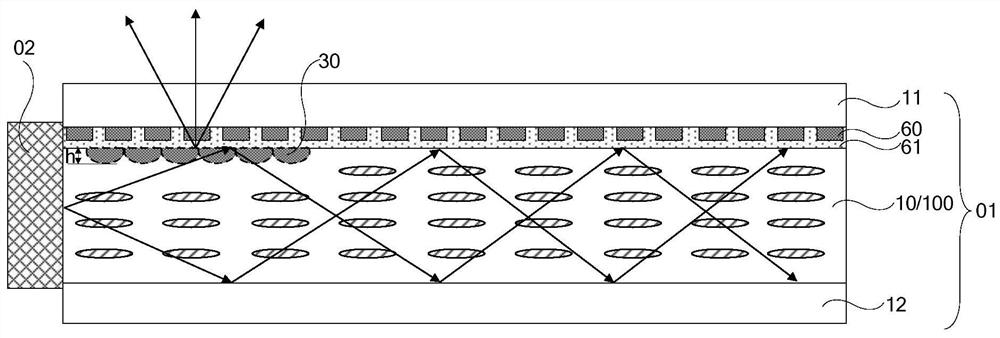
Display panel, display device and control method thereof
A technology for display panels and display devices, applied in static indicators, instruments, optics, etc., can solve the problems of poor performance of polarizers and reduced light transmittance, and achieve the effects of improving mass production and contrast.
- Summary
- Abstract
- Description
- Claims
- Application Information
AI Technical Summary
Problems solved by technology
Method used
Image
Examples
Embodiment approach 1
[0087] Regarding this method, in this embodiment, the light source 02 is used to emit white light, and the above-mentioned sub-pixels 101 are arranged in the display area of the display panel 01 .
[0088] In this case, if Figure 8 As shown, in this embodiment, the above-mentioned display panel further includes a color filter layer 40 , and the color filter layer 40 is disposed on the first substrate 11 . The color filter layer 40 includes a plurality of filter units 401 . Each sub-pixel 101 has a filter unit 401 inside.
[0089] Wherein, at least three adjacent sub-pixels 101 may form a pixel. The filter units 401 of different sub-pixels 101 in the same pixel may be different or the same, which is not limited in this application. Taking three sub-pixels 101 in the same pixel as an example, and the filter units 401 of the three sub-pixels 101 are different, for example, the three sub-pixels 101 in the pixel respectively correspond to the red (R) filter unit 401, Green (...
Embodiment approach 2
[0092] In this embodiment, the above-mentioned light source 02 is used to emit white light, and the above-mentioned sub-pixels 101 are disposed in the display area of the display panel 01 .
[0093] In this case, it can be seen from the above that at least three adjacent sub-pixels 101 may constitute one pixel.
[0094] Such as Figure 9 As shown, the number of first sub-electrodes 210 in different sub-pixels 101 in the same pixel is different. Therefore, by adjusting the number of first sub-electrodes 210 in one first electrode 21 in the sub-pixel 101, that is, the width and spacing of the first sub-electrodes 210 in the first electrode 21, different sub-pixels 101 can be in a fixed Light rays with different wavelengths are diffracted in the outgoing direction, thereby realizing color display.
[0095] Specifically, the sub-pixel 101 is used to emit light of wavelength λ. Wherein, the incident angle θ of the light in the waveguide layer 10 incident on the light-incident ...
Embodiment approach 3
[0120] In this embodiment, if Figure 11 As shown, the above-mentioned light source 02 is used to emit multiple monochromatic lights in time division. In addition, in the case where the display panel 01 of the display device has the sub-pixels 101 for emitting multiple kinds of monochromatic light with the same period as above, in the case that an independent liquid crystal grating 30 can be formed, the above step S101 includes: During the period T, the above-mentioned light source 02 sequentially emits different monochromatic lights, for example, sequentially emits three primary colors of R, G, and B lights, and the different monochromatic lights emitted in one lighting cycle can be mixed into white light.
[0121] It should be noted that, the above-mentioned duration of one lighting period T is less than or equal to the duration of one picture frame.
[0122] Specifically, the above-mentioned light source 02 is provided with multiple kinds, for example, red (R), green (G) a...
PUM
| Property | Measurement | Unit |
|---|---|---|
| refractive index | aaaaa | aaaaa |
| refractive index | aaaaa | aaaaa |
| refractive index | aaaaa | aaaaa |
Abstract
Description
Claims
Application Information
 - R&D
- Intellectual Property
- Life Sciences
- Materials
- Tech Scout
- Unparalleled Data Quality
- Higher Quality Content
- 60% Fewer Hallucinations
Browse by: Latest US Patents, China's latest patents, Technical Efficacy Thesaurus, Application Domain, Technology Topic, Popular Technical Reports.
© 2025 PatSnap. All rights reserved.Legal|Privacy policy|Modern Slavery Act Transparency Statement|Sitemap|About US| Contact US: help@patsnap.com


