
Intelligent control device and method for concrete manual vibration fluctuation

A technology of intelligent control and control method, which is applied to the analysis of solids, buildings, and building structures using sound waves/ultrasonic waves/infrasonic waves. Effect

Pending Publication Date: 2020-01-31
CHINA POWER CONSRTUCTION GRP GUIYANG SURVEY & DESIGN INST CO LTD
View PDF8 Cites 0 Cited by
  • Summary
  • Abstract
  • Description
  • Claims
  • Application Information

AI Technical Summary

Problems solved by technology

The disadvantage of this method is that only the moving track of the artificial vibrator can be obtained, and it is not known whether it is vibrating or not; the positioning accuracy is greater than nanosecond level, which is greatly limited by the radio signal receiving device and synchronous controller.

Method used


Image

  • Intelligent control device and method for concrete manual vibration fluctuation
  • Intelligent control device and method for concrete manual vibration fluctuation

Examples


Embodiment Construction

[0017] The present invention will be further described below in conjunction with the accompanying drawings and embodiments, but not as a basis for limiting the present invention.

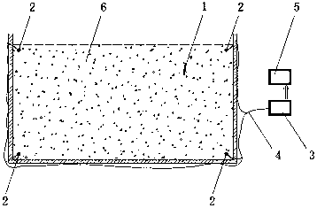
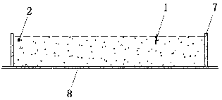
[0018] Example. An intelligent control device for artificial vibration of concrete, which is composed of figure 1 and 2 As shown, it includes a vibration signal sensor 2 for receiving the vibration signal of the vibrator 1, the vibration signal sensor 2 is connected to the acoustic wave instrument 3, and the acoustic wave instrument 3 is connected to the system 5 for collecting and processing the wave signal. Between the vibration signal sensor 2 and the acoustic wave instrument 3, and the acoustic wave instrument 3 and the acquisition and fluctuation signal processing system 5 can be connected by a wire 4 (such as figure 1 As shown), it can also be connected through the wireless network module, which can be selected according to actual needs.

[0019] The aforementioned vibration signal sensors ...


PUM


Abstract

The invention discloses an intelligent control device and method for concrete manual vibration fluctuation. The device comprises a vibration signal sensor (2) used for receiving vibration signals of avibrating rod (1), the vibration signal sensor (2) is connected with an acoustic wave instrument (3), and the acoustic wave instrument (3) is connected with an acquisition and fluctuation signal processing and mapping system (5). When artificial concrete is vibrated, the position and the vibrating time of an artificial vibrating point can be obtained in real time, the vibrating operation is recorded and monitored in real time, and the purposes that vibration leakage and excessive vibration are avoided in the vibrating construction, and the process is controllable and traceable are achieved.

Description

technical field [0001] The invention relates to the technical field of intelligent buildings, in particular to an intelligent control device and control method for artificial vibration of concrete. Background technique [0002] At this stage, the real-time monitoring of concrete pouring vibration includes GPS dynamic positioning and radio signal positioning. For example: ①GPS dynamic positioning "concrete pouring vibrating dynamic visual monitoring method" (CN 102444289B), is a vibrator point working trajectory determination system based on GPS dynamic positioning test, through real-time acquisition and transmission, processing the vibrator point operation on the concrete pouring site Trajectory state parameter information, and use computer graphics online method to display for real-time monitoring. It is characterized by using GPS positioning and the potential value when the vibrating rod is inserted and pulled out of the concrete to determine the vibrating time. The disad...

Claims


Application Information

Patent Timeline
Patent Type & Authority Applications(China)
IPC IPC(8): G01N29/07E04G21/08
CPCG01N29/07E04G21/08
Inventor 尹曜华李准姚斌
Owner CHINA POWER CONSRTUCTION GRP GUIYANG SURVEY & DESIGN INST CO LTD
Learn More