
Damping machine base for mounting electromechanical equipment

A technology for electromechanical equipment and installation, which is applied in the field of shock-absorbing bases for installation of electromechanical equipment, can solve the problems of poor shock-absorbing effect of shock-absorbing bases, and achieve the effects of improving shock-absorbing effect, improving fluency, and reducing frictional resistance.

Inactive Publication Date: 2020-01-31
宝鸡市捷龙商贸有限公司
View PDF6 Cites 5 Cited by
  • Summary
  • Abstract
  • Description
  • Claims
  • Application Information

AI Technical Summary

Problems solved by technology

[0003] The existing electromechanical equipment needs to be installed with a shock-absorbing base during installation, and the existing shock-absorbing base has a poor shock-absorbing effect during use

Method used


Image

  • Damping machine base for mounting electromechanical equipment
  • Damping machine base for mounting electromechanical equipment
  • Damping machine base for mounting electromechanical equipment

Examples


Embodiment 1

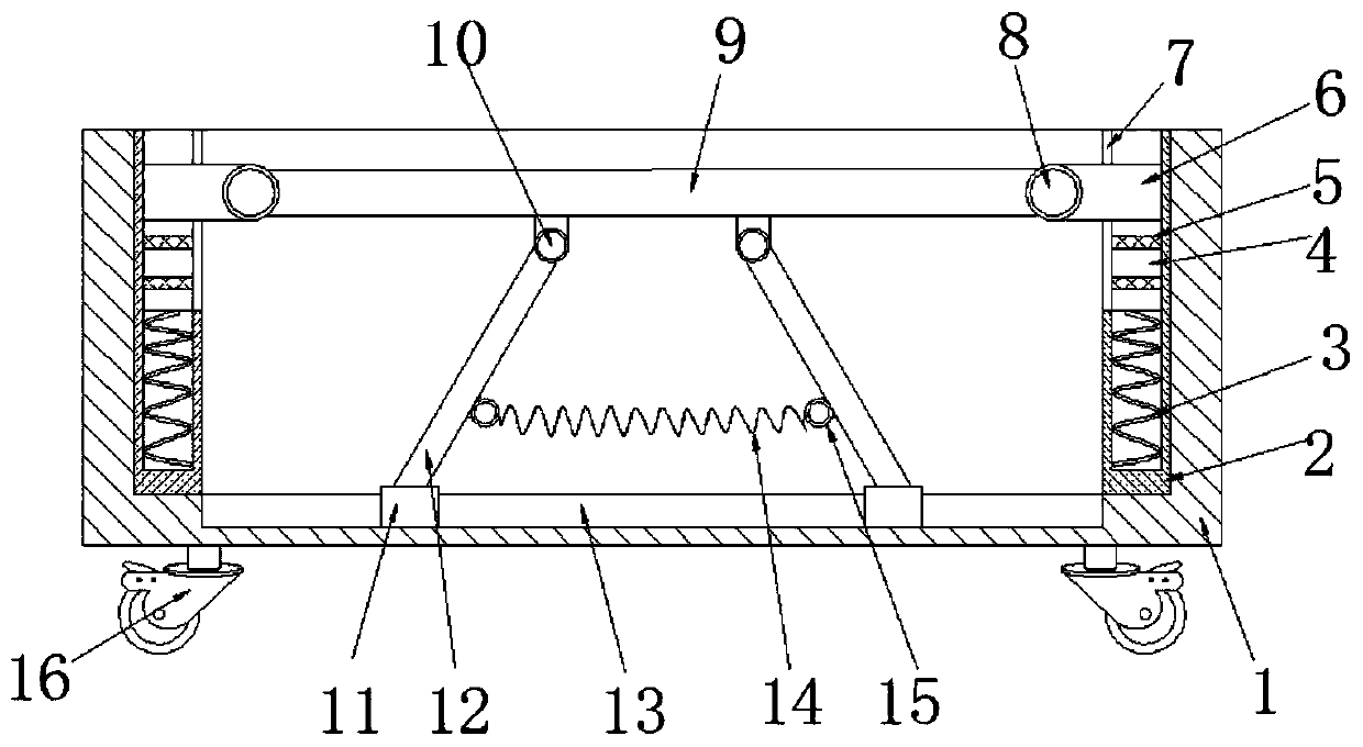
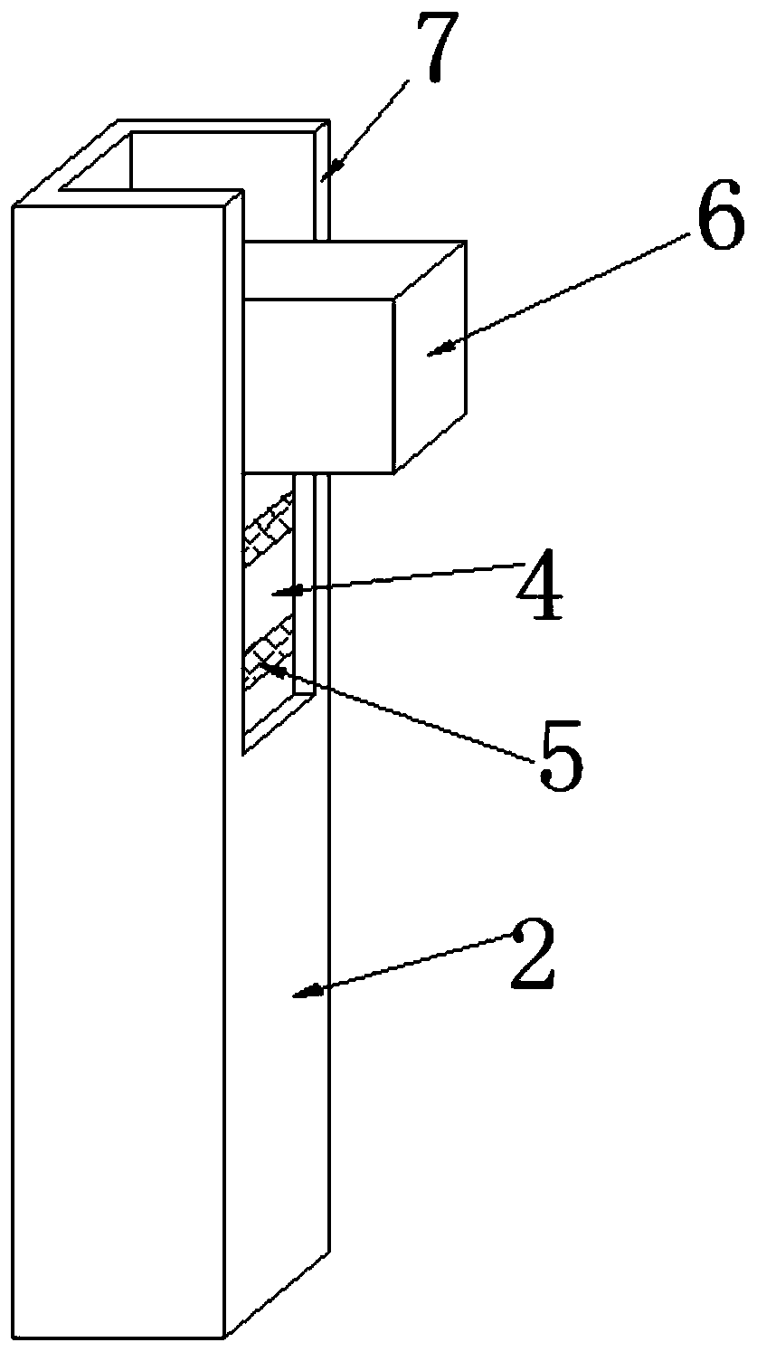
[0025] refer to figure 1 and figure 2 , a shock-absorbing machine base for installing electromechanical equipment, including a box body 1, a casing 2 is fixed at four corners inside the box body 1, and a support spring 3 is fixed inside the casing 2, and the outer wall of the casing 2 is opened. There is a movable port 7, a piston 4 is movably inserted in the casing 2, and a plurality of annular grooves are opened on the piston 4, and a rubber ring 5 that fits the inner wall of the casing 2 is embedded in the annular groove, and the top of the piston 4 is fixed. There are sliders 6 that form snap fit with the movable opening 7, and one end of the four sliders 6 is fixed with connecting ears 8, and the same storage board 9 is fixed between the connecting ears 8, and the outer wall of the bottom of the storage board 9 is fixed with two symmetrical Distributed shaft sleeves 10, support rods 12 are rotatably inserted in the shaft sleeves 10, and a reset mechanism is fixed betwee...

Embodiment 2

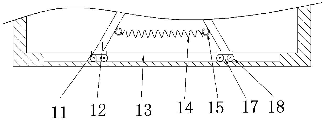
[0029] refer to image 3 , a shock-absorbing machine base for installing electromechanical equipment. The difference between this embodiment and Embodiment 1 is that the outer wall of the bottom of the guide block 11 also has a rolling groove 17, and a roller 18 is installed in the rolling groove 17 for rotation.

[0030] The working principle of this embodiment: the roller 18 can reduce the frictional resistance between the guide block 11 and the guide groove 13 and improve the smoothness of the movement of the guide block 11 .

Embodiment 3

[0032] refer to Figure 4 , a shock-absorbing machine base for installing electromechanical equipment. The difference between this embodiment and Embodiment 1 is that two symmetrically distributed clamping plates 19 are fixed on the outer wall of the top of the storage plate 9, and the clamping surface of the clamping plate 19 is fixed with Clamping pad 20 .

[0033] The working principle of this embodiment: two clamping plates 19 can be used to clamp the two sides of the electromechanical equipment body installed on the storage plate 9, and the clamping pad 20 can play an anti-slip protection effect on the outer wall surface of the electromechanical equipment body, improving The stability of clamping work.


PUM


Abstract

The invention discloses a damping machine base for mounting electromechanical equipment. The damping machine base comprises a box body, sleeves are fixed to the four corners in the box body, supporting springs are fixed in the sleeves, movable openings are formed in the outer walls of one sides of the sleeves, piston are movably connected in the sleeves in an inserted mode, a plurality of annulargrooves are formed in the pistons, rubber rings attached to the inner walls of the sleeves are connected in the annular grooves in an embedded mode, sliding blocks in clamping fit with the movable openings are fixed t the top ends of the pistons, connecting lugs are fixed to one ends of the four sliding blocks, an object placing plate is fixedly arranged between every two connecting lugs, two shaft sleeves which are symmetrically distributed are fixed to the outer wall of the bottom of each object placing plate, supporting rods are rotatably connected in the shaft sleeves in an inserted mode,and a resetting mechanism is fixedly arranged between every two supporting rods. The damping machine base has the advantages that the installation work of the electromechanical equipment is facilitated, and in addition, the integral damping effect can be improved.

Description

technical field [0001] The invention relates to the technical field of shock absorbing equipment, in particular to a shock absorbing base for installing electromechanical equipment. Background technique [0002] Electromechanical equipment generally refers to machinery, electrical appliances, and electrical automation equipment. In construction, it refers to the general term for machinery and pipeline equipment other than geotechnical, carpentry, steel bars, and muddy water. It is different from hardware and mostly refers to finished products that can achieve certain functions. With the continuous improvement of people's living standards, people's demand for electromechanical equipment in daily life is increasing. From transportation to various household appliances, computers, printers, etc., electromechanical products have become indispensable in people's life. Advanced mechanical and electrical equipment can greatly increase labor productivity, reduce labor intensity, imp...

Claims


Application Information

Patent Timeline
Patent Type & Authority Applications(China)
IPC IPC(8): F16F15/08F16M11/04
CPCF16F15/085F16M11/04
Inventor 李峰
Owner 宝鸡市捷龙商贸有限公司
Learn More