Method for controlling fuel metering system

A technology of fuel metering and fuel temperature, which is applied in the direction of charging system, electrical control, fuel injection pump, etc.

Pending Publication Date: 2020-01-31
ROBERT BOSCH GMBH
View PDF8 Cites 0 Cited by
  • Summary
  • Abstract
  • Description
  • Claims
  • Application Information

AI Technical Summary

Problems solved by technology

However, cold fuel is not completely vaporized when injected into the combustion chamber, whereby wetting of the piston or combustion chamber walls may occur

Method used


Image

  • Method for controlling fuel metering system
  • Method for controlling fuel metering system

Examples


Embodiment Construction

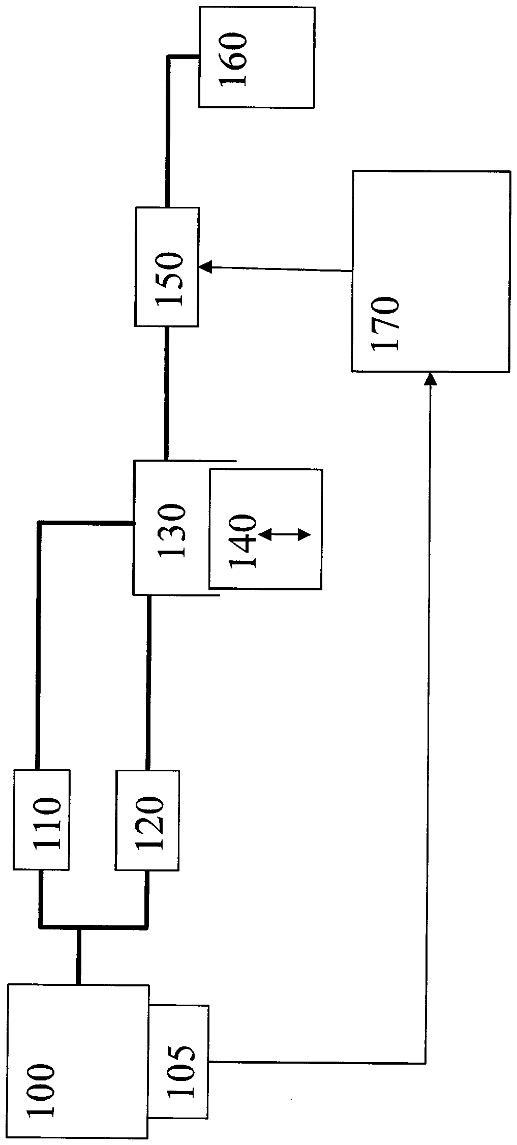
[0011] figure 1 The main elements of a fuel metering system of a fuel supply system of an internal combustion engine are shown. Use 100 to represent rails. Fuel passes from this rail 100 via injectors (not shown) into the combustion chamber of the internal combustion engine. The pressure P in the rail 100 , also referred to as rail pressure, is detected by the sensor 105 . The rail 100 is connected via a pressure limiting valve 110 and an outlet valve 120 to a delivery chamber 130 , ie a high-pressure pump. The fuel in delivery chamber 130 is compressed by piston 140 . For this purpose, the piston is driven by a drive unit from the camshaft or crankshaft of the internal combustion engine and expands and contracts the delivery chamber 130 by moving it back and forth.

[0012] Pressure limiting valve 110 is designed such that it releases the connection between the rail and delivery chamber 130 when the pressure in rail 100 exceeds a certain threshold value. Outlet valve 120...


PUM


Abstract

A method for controlling a fuel metering system is described. The flow control valve is energized to increase the fuel temperature before the motor is started.

Description

technical field [0001] The invention relates to a method for controlling a fuel metering system. Background technique [0002] Methods for controlling fuel metering systems are known. For combustion motors with a high-pressure injection system, the cold start requires the motor to start by building up pressure in the fuel accumulator. In this case, the temperature of the fuel corresponds to the temperature of the environment after a relatively long shutdown phase. However, cold fuel is not completely vaporized when it is injected into the combustion chamber, so that wetting of the piston or the walls of the combustion chamber can occur. As a result, more carbon black particles are produced during the combustion process. The amount of carbon black particles should be kept as low as possible. Contents of the invention [0003] In contrast, the method according to the invention having the features of the independent claim has the advantage that the number of soot particle...

Claims


Application Information

Patent Timeline
Patent Type & Authority Applications(China)
IPC IPC(8): F02D1/02F02M59/34F02M59/10
CPCF02D1/02F02M59/34F02M59/10F02D41/064F02D2200/50F02D2200/0602F02D2041/2065F02D41/20F02D41/3845F02D2041/1412
Inventor T.赫格斯
Owner ROBERT BOSCH GMBH
Why Eureka
Try Eureka