Sucking and throwing separated type steering granary flattening robot

A robot and steering device technology, applied in the field of warehouse closing robots, can solve problems such as poor working environment, inability to meet the use requirements, and inability to give full play to the advantages of equipment

Pending Publication Date: 2020-01-31
SHANDONG INSPUR GENESOFT INFORMATION TECH CO LTD
View PDF0 Cites 1 Cited by
  • Summary
  • Abstract
  • Description
  • Claims
  • Application Information

AI Technical Summary

Problems solved by technology

[0002] At present, the closing work of grain depots in my country basically relies on manual work. Not only is the workload heavy, the closing time is slow, and the time is long, but also the labor intensity is high, the working environment is harsh, no one wants to do it, the cost is high, and the quality of closing is difficult to guarantee; therefore , the use of unwinding equipment to replace manual operations to improve work efficiency, reduce operating costs and reduce labor intensity is an urgent market demand
However, at present, the functions of the liquidation equipment on the market are relatively single, and the versatility is relatively poor. Although the liquidation robot products have been launched one after another, there are also great defects and deficiencies.
The defects of existing warehouse closing robots include: on the one hand, the auger mechanism and the grain throwing mechanism are both fixed on the same frame, and a steering mechanism is provided at the bottom of the frame. The direction or the direction of the auger can be adjusted separately, which cannot meet the requirements of complex working scenarios in the warehouse. For example, when absorbing grain from a certain grain pile, the structure can only throw grain to the opposite direction of the grain pile. If the opposite direction is also a grain pile , then the operation at this time is invalid; on the other hand, the adjustment function of the throwing distance of this type of equipment is realized by adjusting the motor speed to adjust the initial speed of grain throwing. The smaller the height, the higher the speed, the greater the distance and height of the conveyor belt throwing grain. Therefore, when throwing grain at a short distance, the working efficiency of the equipment is relatively low, and the advantages of equipment replacing labor cannot be fully utilized.

Method used


Image

  • Sucking and throwing separated type steering granary flattening robot
  • Sucking and throwing separated type steering granary flattening robot
  • Sucking and throwing separated type steering granary flattening robot

Examples


Embodiment

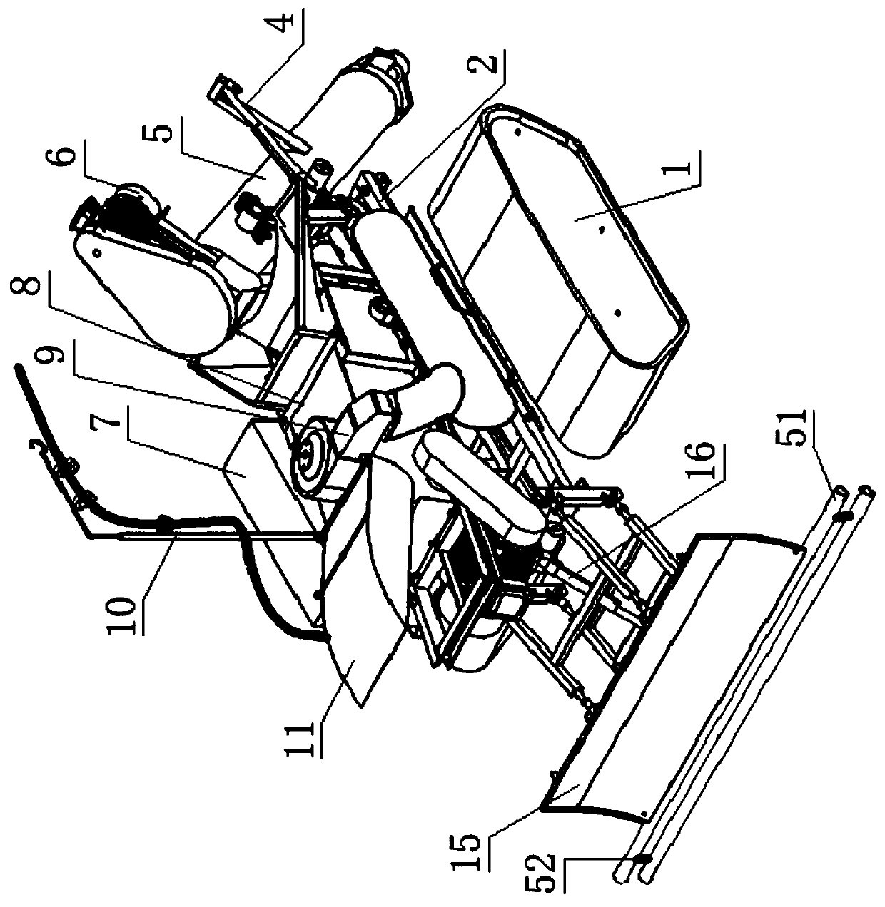
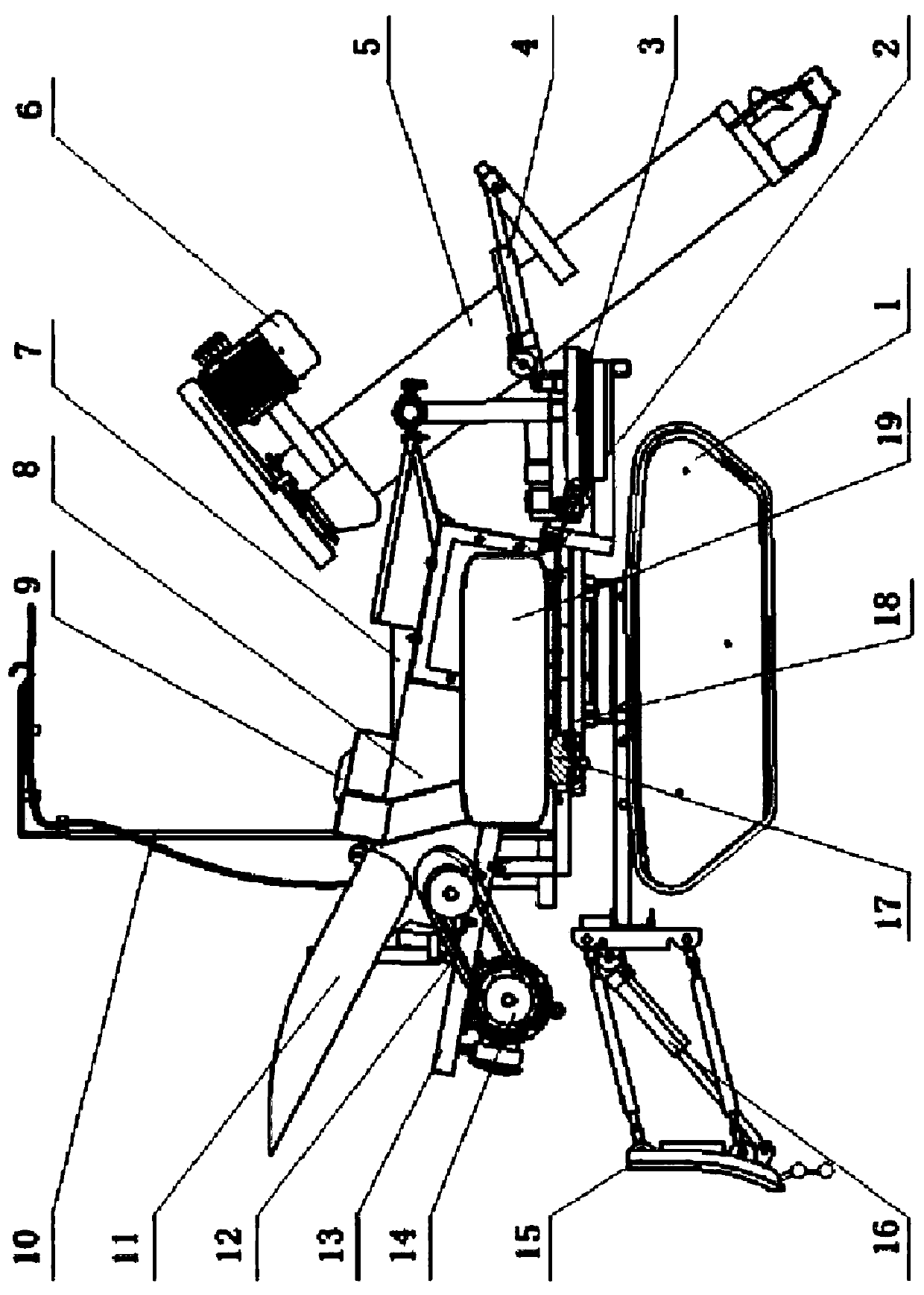
[0088] A steering-type unwinding robot that separates pumping and throwing according to the present invention includes a bottom bracket, a grain-absorbing auger device 5 , a grain-throwing conveyor belt device 8 , a grain-leveling device, a walking device 1 and a control device 7 .

[0089] Among them, there are two running devices 1, both of which are crawler-type running devices 1, and the two running devices 1 are arranged side by side on both sides of the bottom bracket at intervals, and are used to drive the bottom bracket to walk.

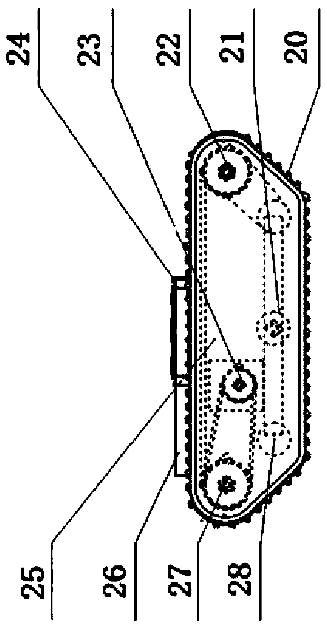
[0090]In this embodiment, the traveling device 1 is mainly composed of crawler belts 20 , supporting wheels 21 , guide wheels 22 , crawler belt drive motors 23 , bottom frames 24 , driving wheels 27 and supporting wheels 28 . The supporting wheel 21, the guiding wheel 22, the driving wheel 27 and the supporting wheel 28 are all rotatably assembled on the bottom frame 24, and the track drive is connected between the supporting wheel 21, the gui...


PUM


Abstract

The invention discloses a sucking and throwing separated type steering granary flattening robot, and belongs to the field of granary flattening robots. The technical problems of how to separate an auger mechanism from a grain throwing mechanism and to give up dependence on staff are solved. The sucking and throwing separated type steering granary flattening robot structurally comprises a bottom bracket, a grain sucking auger device, a grain throwing conveying belt device, a grain flattening device, two traveling devices and a control device, wherein the bottom bracket comprises a head installation frame and a tail installation frame connected with the head installation frame end to end, and both the head installation frame and the tail installation frame are provided with steering devices;the grain sucking auger device is arranged on the tail installation frame through the corresponding steering device; the grain throwing conveying belt device is arranged on the head installation frame through the corresponding steering device; the grain flattening device is arranged on the head side of the head installation frame and located below the grain throwing conveying belt device; the twotraveling devices are both tracked traveling devices and are installed in a spaced mode, arranged on the two sides of the bottom bracket and used for driving the bottom bracket to move; and the control device is connected with the steering device, the grain sucking auger device, the grain throwing conveying belt device, the grain flattening device and the traveling devices.

Description

technical field [0001] The invention relates to the field of liquidation robots, in particular to a steering type liquidation robot that separates pumping and throwing. Background technique [0002] At present, the closing work of grain depots in my country basically relies on manual work. Not only is the workload heavy, the closing time is slow, and the time is long, but also the labor intensity is high, the working environment is harsh, no one wants to do it, the cost is high, and the quality of closing is difficult to guarantee; therefore There is an urgent market demand for using unwinding equipment to replace manual operations to improve work efficiency, reduce operating costs and reduce labor intensity. However, at present, the functions of the liquidation equipment on the market are relatively single, and the versatility is relatively poor. Although the liquidation robot products have been launched one after another, they also have great defects and deficiencies. The ...

Claims


Application Information

Patent Timeline
IPC IPC(8): B65G69/04B65G69/18B65G69/16
CPCB65G69/0466B65G69/0433B65G69/045B65G69/182B65G69/16B65G2201/0202
Inventor 傅慧邵辉张超
Owner SHANDONG INSPUR GENESOFT INFORMATION TECH CO LTD
Why Eureka
Try Eureka