Automatic component glue filling device of LED driver

A LED driver and glue filling technology, which is applied in the direction of surface coating liquid devices, semiconductor devices, electrical components, etc., can solve the problems of different glue flow filling rates, excess glue, overflow glue or less glue, and accelerate the glue in the LED driver. Problems such as flow filling rate to achieve the effect of improving the degree of automation, avoiding excess glue, and speeding up the rate of flow and bottom sinking

Active Publication Date: 2020-01-31
ZHEJIANG KAIYAO LIGHTING
View PDF9 Cites 0 Cited by
  • Summary
  • Abstract
  • Description
  • Claims
  • Application Information

AI Technical Summary

Problems solved by technology

[0005] The present invention overcomes the fact that the high viscosity of the colloid in the prior art causes the flow filling rate of the colloid to be different, and the existing automatic glue filling device cannot accurately grasp the balance between the glue filling time of the LED driver and the actual glue filling amount one by one, resulting in The technical problem of excessive glue, overflowing glue or less glue is likely to occur in the finished product of the LED driver. A component automatic glue filling device for the LED driver is provided. The vibration module in the device drives the LED driver to be glued to vibrate synchronously. Accelerate the flow filling rate of the colloid in the LED driver, the colloid that is first filled into the LED driver quickly fills the bottom of the LED driver, and the subsequent colloids injected into the LED driver fill the LED driver quickly in sequence, and there will be no cavity occupying the volume in the LED driver. At the same time, the liquid level detector monitors the colloid liquid level inside the LED driver in real time, thus effectively avoiding the phenomenon of excess glue, overflow glue or less glue

Method used


Image

  • Automatic component glue filling device of LED driver
  • Automatic component glue filling device of LED driver
  • Automatic component glue filling device of LED driver

Examples


Embodiment

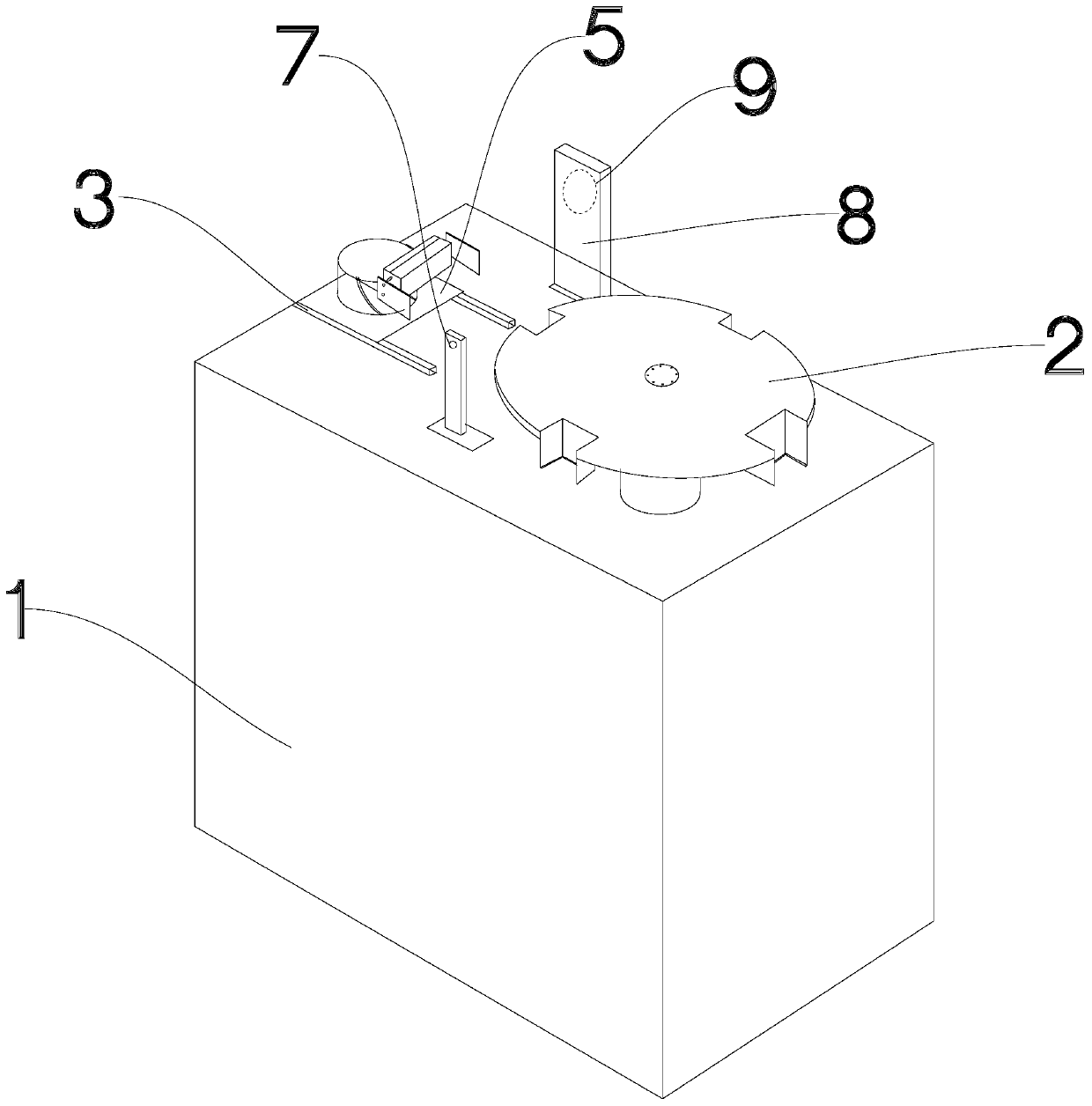
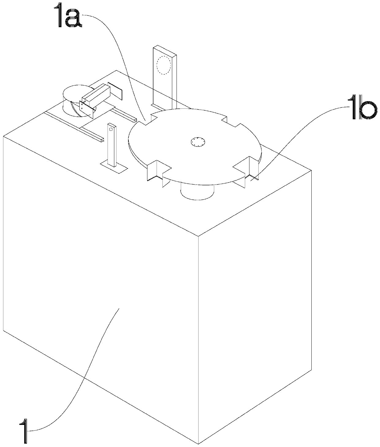
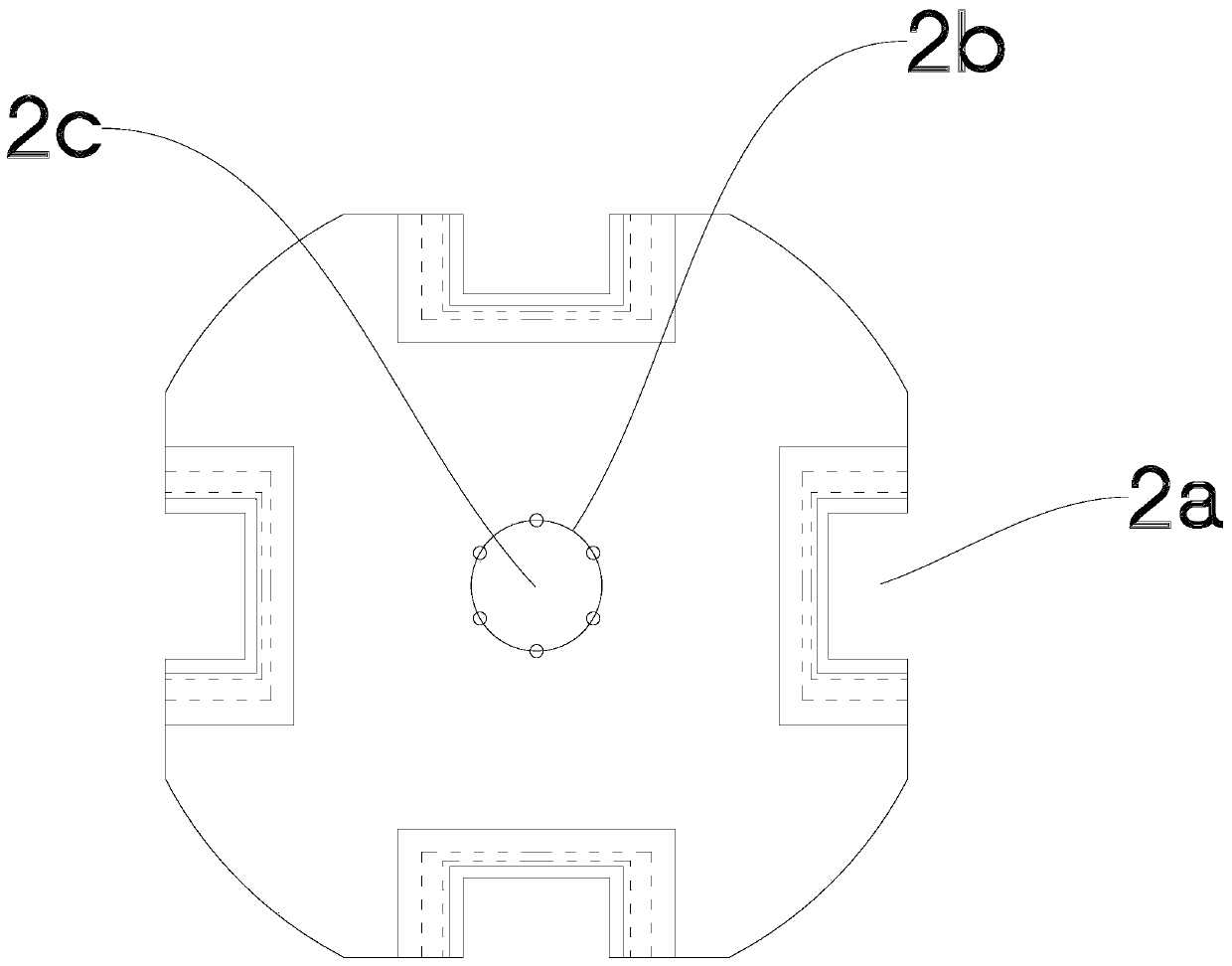
[0033] Such as Figure 1 to Figure 5 As shown, a component automatic glue filling device for LED drivers includes a workbench 1 on which an indexing turntable 2 is arranged. The radially symmetrical arrangement of the workbench is equipped with a linear movement module on the side close to the glue filling station. Driven by the power module, the linear movement module can move close to or away from the glue filling station. The linear movement module The upper part is provided with a vibration module 12 and a clamping module 13 for clamping the LED driver in sequence. The clamping module is located above the vibration module, and the indexing turntable is driven by the power module to drive the LED driver from loading and unloading. When the station turns to the glue filling station, the clamping module is driven by the linear movement module to approach the LED driver and clamp it. The liquid level detector on the side of the glue filling station monitors the liquid level o...


PUM


Abstract

The invention discloses an automatic component glue filling device of an LED driver, and aims to solve the technical problem that in the prior art, a finished product of the LED driver is prone to generate excessive glue, excessive glue or insufficient glue. The automatic component glue filling device comprises a workbench, wherein an indexing rotary disc is arranged on the workbench; a glue filling station, a feeding station and a discharging station on the workbench are symmetrically arranged in the radial direction of the indexing rotary disc; a linear moving module is arranged on one side,close to the glue filling station, of the workbench; the linear moving module can move close to or away from the glue filling station under the driving of a power module; a vibration module and a clamping module are arranged on the linear moving module; when the indexing rotary disc drives the LED driver to rotate from the feeding station and the discharging station to the glue filling station under the driving of the power module, the clamping module is driven by the linear moving module to be close to the LED driver, and a liquid level detector arranged on the side face of the glue fillingstation monitors the liquid level of a glue filling opening of the LED driver while the glue filling module arranged above the workbench is used for filling glue to the LED driver.

Description

technical field [0001] The invention relates to the technical field of LED driver production and processing, in particular to a component automatic glue filling device for the LED driver. Background technique [0002] LED lighting is a new type of light source that has developed rapidly in recent years, and its many good features make it more and more widely used. LED is a kind of electric light source with extremely long service life, and its service life can reach 100,000 hours. Due to the one-way conduction characteristic of LED, LED must be equipped with LED driving circuit to work. With the gradual development of LED lighting fixtures, the requirements and consumption of lighting fixtures for LED drive power have also increased significantly. LED drive power must have the advantages of high efficiency, high power factor, and high protection functions. Therefore, the research and development of LED drive power Production and use are also constantly being valued. Among ...

Claims


Application Information

Patent Timeline
Patent Type & Authority Applications(China)
IPC IPC(8): B05C5/00B05C11/10B05C13/02H01L33/00
CPCB05C5/00B05C11/10B05C13/02H01L33/00
Inventor 金文明杨治法侯正正
Owner ZHEJIANG KAIYAO LIGHTING
Why Eureka
Try Eureka