Glass cleaning device for control room of waste incineration power plant

A glass cleaning and waste incineration technology, applied in applications, cleaning equipment, household appliances, etc., can solve the problems of short service life, low reliability, affecting the observation and operation of operators, and achieve the effect of long service life and simplified moving mechanism.

Pending Publication Date: 2020-01-31
CHINA CITY ENVIRONMENT PROTECTION ENGINEERING LIMITED COMPANY
View PDF0 Cites 0 Cited by
  • Summary
  • Abstract
  • Description
  • Claims
  • Application Information

AI Technical Summary

Problems solved by technology

Due to the harsh environment of the garbage pit, in order to facilitate the operation of the grab, the partition surface in front of the control room is generally set to transparent glass, but because the glass outer wall is located in the garbage pit, it is easy to be stained and affect the observation operation of the operator, so it needs to be cleaned in time
However, none of the existing cleaning devices can adapt to such a harsh environment, with low reliability and short service life

Method used


Image

  • Glass cleaning device for control room of waste incineration power plant
  • Glass cleaning device for control room of waste incineration power plant
  • Glass cleaning device for control room of waste incineration power plant

Examples


specific Embodiment

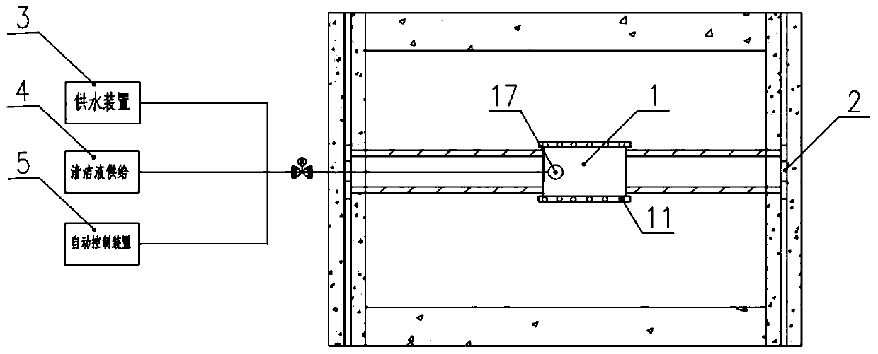
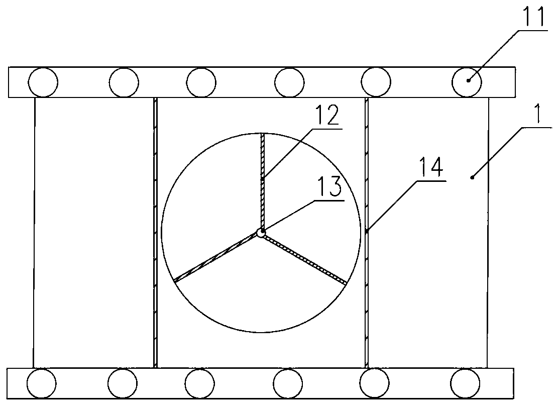
[0023] For details on cleaning component 1 above, see figure 1 and image 3 , the cleaning assembly 1 includes a cleaning plate driven by the second driving assembly, a rotating cleaning piece 12 mounted on the cleaning plate, and a spray head 13 for spraying cleaning liquid or water, and the spray head 13 is installed on the cleaning plate. On the rotary cleaning element 12 described above. In this embodiment, the cleaning method is to use rotary cleaning. During the rotation of the rotary cleaning member 12, the stains on the glass are cleaned. The nozzle 13 can spray cleaning liquid on the glass before cleaning, so as to facilitate cleaning. After cleaning, spray water to rinse off the stains. Installing the spray head 13 on the rotating cleaning element 12 can most directly spray the liquid to the area to be cleaned. Preferably, a sponge is placed at the bottom of the cleaning assembly 1, specifically, a sponge is placed at the bottom of the cleaning plate, and a cleani...


PUM


Abstract

The invention relates to the technical field of waste incineration, and provides a glass cleaning device for a control room of a waste incineration power plant. The glass cleaning device comprises a cleaning component; the glass cleaning device further comprises two parallel vertical guide rails arranged along the height direction of glass to be cleaned, a horizontal guide rail arranged between the two vertical guide rails, a first driving component for driving the horizontal guide rail to move along the height direction of the glass to be cleaned and a second driving component for driving thecleaning component to move on the horizontal guide rail; two vertical guide rails are arranged at intervals; and the two sides of the horizontal guide rail are slidably arranged on the two vertical guide rails respectively. According to the glass cleaning device for the control room of the waste incineration power plant provided by the invention, a moving frame of the cleaning component is constructed through the vertical guide rails and the horizontal guide rail, a moving mechanism of the cleaning component is simplified, the cleaning device is firm and reliable, and the service life is long.

Description

technical field [0001] The invention relates to the technical field of waste incineration, in particular to a glass cleaning device for the control room of a waste incineration power plant. Background technique [0002] In order to realize waste reduction and resource disposal, incinerating waste to generate electricity is a practical and feasible method for the current society. Waste incineration power plants generally have a control room at the garbage pit, and the garbage in the garbage pit is thrown into the incinerator through a manually controlled grab bucket. Due to the harsh environment of the garbage pit, in order to facilitate the operation of the grab, the partition surface in front of the control room is generally set to transparent glass, but because the glass outer wall is located in the garbage pit, it is easy to be stained and affect the observation operation of the operator, so it needs to be cleaned in time . However, none of the existing cleaning devices...

Claims


Application Information

Patent Timeline
IPC IPC(8): A47L1/02
CPCA47L1/02
Inventor 朱林庞路朱飞肖汉平樊飞勇张浩浩胡晓炜张瑶
Owner CHINA CITY ENVIRONMENT PROTECTION ENGINEERING LIMITED COMPANY
Why Eureka
Try Eureka