Rotatable lifting camera and display device

A technology of rotating lift and camera, applied in image communication, instruments, TV and other directions, can solve the problem that the camera angle cannot be automatically adjusted, and achieve the effect of simple product appearance, avoiding privacy leakage, and simple appearance

Active Publication Date: 2020-10-13
ONEPLUS TECH SHENZHEN
View PDF13 Cites 0 Cited by
  • Summary
  • Abstract
  • Description
  • Claims
  • Application Information

AI Technical Summary

Problems solved by technology

[0003] Cameras on home appliances and electronic devices are usually fixed on the frame with the screen side. With the development of full-screen applications, home appliances and electronic devices have begun to be equipped with cameras that can be raised and lowered, but the camera angle cannot be adjusted automatically.

Method used


Image

  • Rotatable lifting camera and display device
  • Rotatable lifting camera and display device
  • Rotatable lifting camera and display device

Examples


Embodiment 1

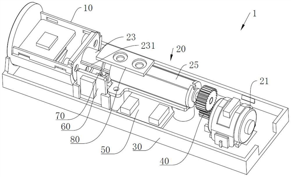
[0039] Such as figure 1 As shown, this embodiment provides a rotatable lifting camera 1, which can be used alone, and is also suitable for devices equipped with cameras. On the display screen of the camera, it includes a camera module 10 and a driving component 20 .

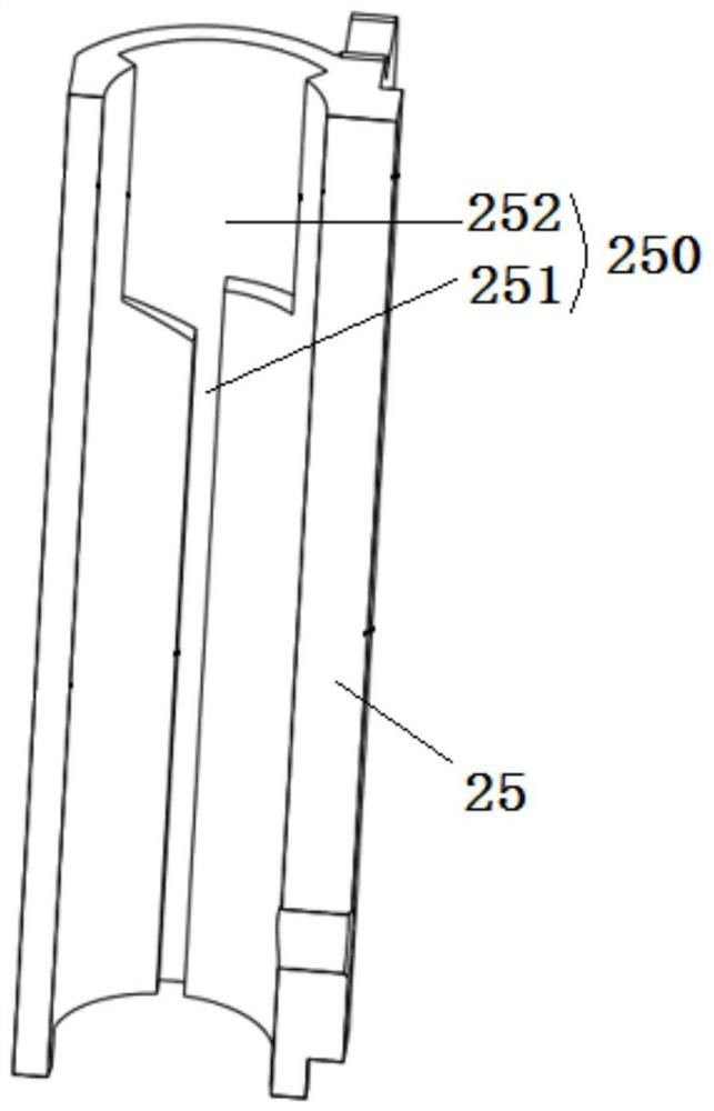
[0040] Please also refer to figure 2 The driving assembly 20 includes a driving member 21 , a transmission member 22 , an actuator 23 , a locking member 24 and a limiting member 25 . The camera module 10 is arranged on the executive part 23 , and a non-rotating sliding fitting section and a rotatable fitting section are formed between the executing part 23 and the limiting part 25 . When the actuator 23 and the limiting member 25 are in the non-rotational sliding fit section, the driving member 21 can drive the actuator 23 to do reciprocating linear motion through the transmission member 22 . When the actuator 23 and the limiting member 25 are in the rotatable mating section, the locking member 24 locks the r...

Embodiment 2

[0076] Please also refer to Figure 6 to Figure 9 , this embodiment provides a display device, including a display screen 2 and the rotatable lifting camera 1 in embodiment 1, the rotatable lifting camera 1 is fixed on the display screen 2 through a base 30, and the camera module 10 can be opposite to the display screen 2 Stretch out or retract, and can rotate after being stretched out on the display screen 2.

[0077] Therefore, the rotatable lifting camera 1 is a hidden camera that can be rotated after being stretched out. This kind of action logic setting is very suitable for the hidden camera of the display device, so that the camera of the display device can be hidden on the display screen 2. Below / after, it is possible to have a larger camera angle by turning.

[0078] When the camera is not in use, the camera module 10 is hidden inside to avoid leakage of privacy, and the appearance of the product is simpler. When the camera needs to be used, the camera module 10 is s...


PUM


Abstract

The invention provides a rotatable lifting camera and a display device. The rotatable lifting camera includes a camera module and a driving assembly, and the driving assembly includes a driving member, a transmission member, an execution member, a limiting member and a locking member; the camera module is arranged on the executing member, and a non-rotational sliding is formed between the executing member and the restricting member The matching section and the rotatable matching section; when the executive part and the limiting part are in the non-rotating sliding fitting part, the driving part can drive the performing part to do reciprocating linear motion through the transmission part; when the executing part and the limiting part are in the rotatable matching part, the locking part The relative rotation between the transmission part and the execution part is locked, so that the driving part drives the camera module to rotate, and the display device includes a rotatable lifting camera, which is a single power source and double actions that can automatically lift and rotate in sections. A rotating and lifting camera and a display device with a camera that can be extended and retracted relative to a display screen and can be rotated after being extended.

Description

technical field [0001] The present invention relates to the field of imaging devices, in particular to a rotatable lifting camera and a display device. Background technique [0002] At present, cameras are mainly divided into two categories: fixed and mobile: fixed cameras are mainly fixed on the product and directly shoot objects. Sports cameras are generally divided into manual sports and automatic sports. Manually moving cameras require actions such as twisting and pressing to control the position and angle of the camera. The automatic motion camera can realize automatic adjustment of position and angle through motors and other means. [0003] Cameras on home appliances and electronic devices are usually fixed on the frame with the screen side. With the development of full-screen applications, home appliances and electronic devices begin to be equipped with cameras that can be raised and lowered, but the camera angle of the camera cannot be adjusted automatically. Con...

Claims


Application Information

Patent Timeline
Patent Type & Authority Patents(China)
IPC IPC(8): F16M11/08H04N5/225
CPCF16M13/02F16M11/046F16M11/08F16M11/18G03B17/561
Inventor 张勇陈宇宙黄晓东余亚军胡进杨勇黄顺明
Owner ONEPLUS TECH SHENZHEN
Why Eureka
Try Eureka