Combined splicing type roller shaft brush

A spliced, roller-shaft technology, applied in the field of brushes, can solve the problem that the brush roller cannot replace the bristles separately, and achieve the effect of quick combination and convenient disassembly and assembly.

Inactive Publication Date: 2020-01-31
安徽诚德刷业有限公司
View PDF4 Cites 0 Cited by
  • Summary
  • Abstract
  • Description
  • Claims
  • Application Information

AI Technical Summary

Problems solved by technology

[0004] Aiming at the problem that the brush rollers in the prior art cannot replace the bristles separately, the purpose of the present invention is to provide a combined splicing roller shaft brush

Method used


Image

  • Combined splicing type roller shaft brush
  • Combined splicing type roller shaft brush
  • Combined splicing type roller shaft brush

Examples


Embodiment 1

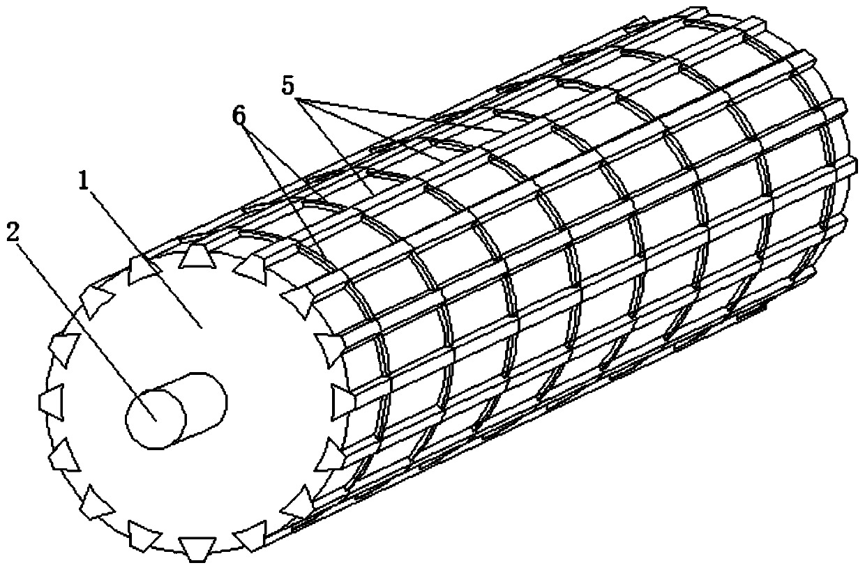
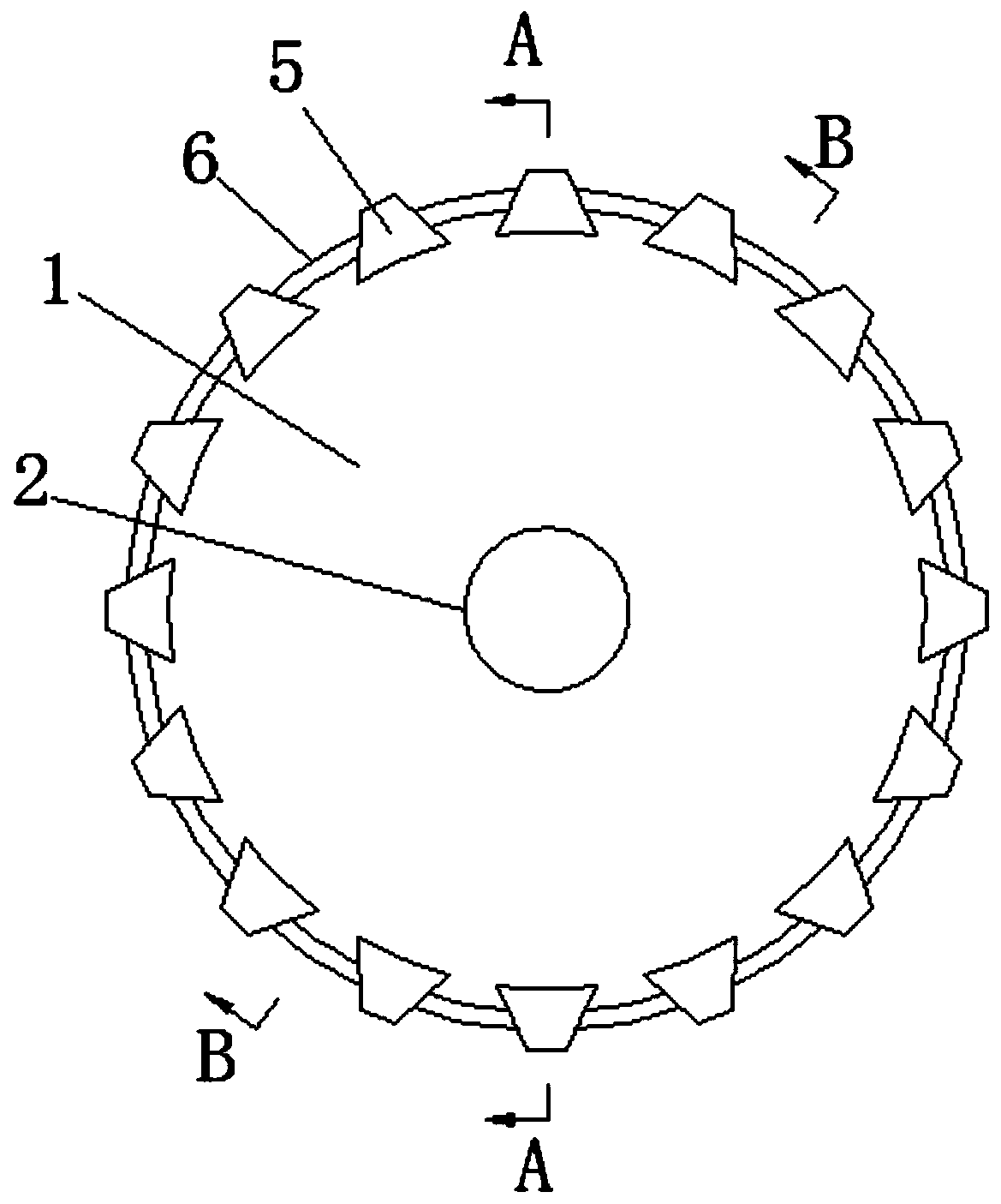
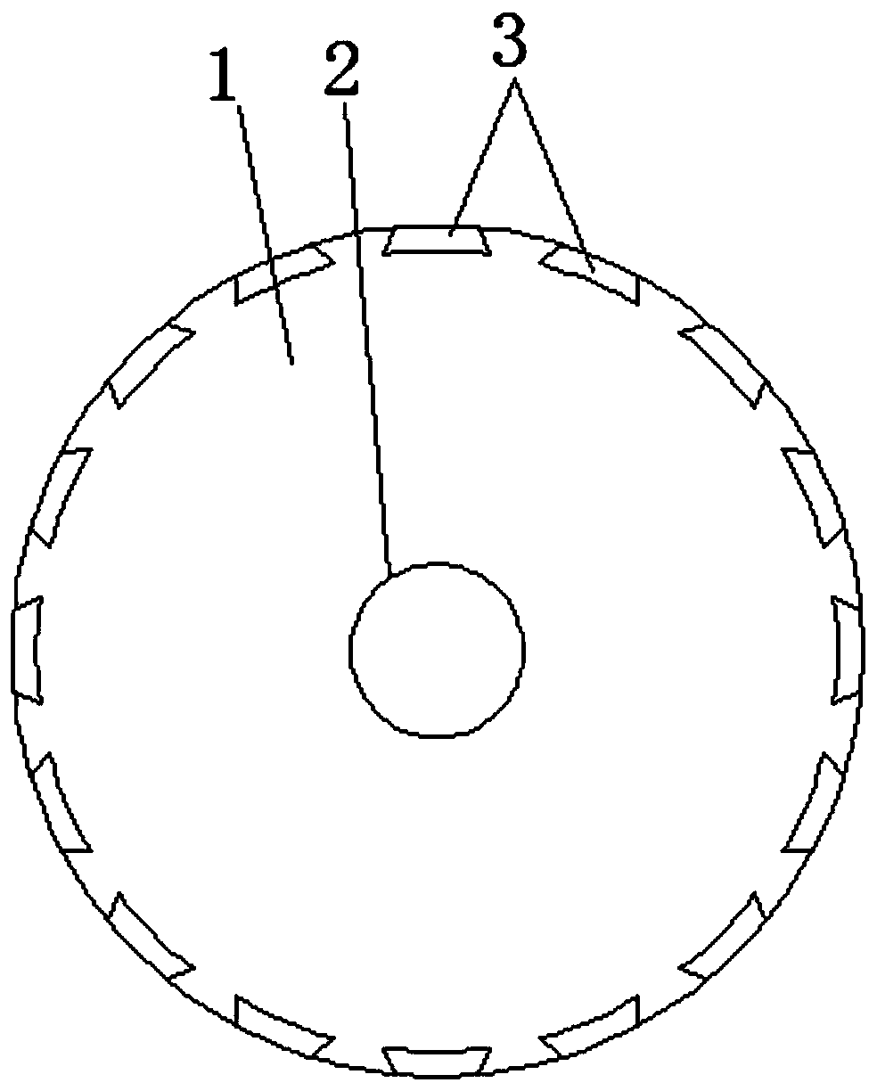
[0023] Such as Figure 1-6 As shown, a combined splicing roller shaft brush includes a roller body 1, a rotating shaft 2 is installed on the roller body 1, and is connected with a power mechanism through the rotating shaft 2, so as to rotate and clean; the circumferential side wall of the roller body 1 is provided with several There are sixteen axial grooves 3 in this embodiment, and the sixteen axial grooves 3 are evenly spaced along the circumferential direction of the roller body 1 .

[0024] The circumferential side wall of the roller body 1 is also provided with several circumferential grooves 4. In this embodiment, there are preferably eight circumferential grooves 4, and the eight circumferential grooves 4 are evenly spaced along the axial direction of the roller body 1;

[0025] In this embodiment, several brush bodies 5 matching the axial grooves 3 are provided in the axial grooves 3 , and bristles (not shown in the figure) are arranged on the brush bodies 5 .

[002...

Embodiment 2

[0031] The difference from Embodiment 1 is that in this embodiment, a first half groove and a second half groove are respectively provided on both ends of the brush body 5, and the first half groove and the second half groove form an arc-shaped through groove. Such arrangement makes the manufacture of the brush body 5 easier under the premise of ensuring that the elastic clip 6 can normally fix the brush body 5 .

Embodiment 3

[0033] The difference from Embodiment 1 is that in this embodiment, the difference between the length of the elastic clip 6 and the circumference of the circumferential groove 4 is greater than the width of the axial groove 3, so that after the elastic clip 6 is installed, it cannot be closed When the notch of the brush is aligned with the axial groove 3, the brush body 5 can not be constrained by it, and can slide in the axial direction; in addition, the difference between the length of the elastic clip 6 and the circumference of the circumferential groove 4 is smaller than that of the axial groove 3, so that when the gap that cannot be closed by the elastic clip 6 is at a certain position (between the two axial grooves 3), all the brush bodies 5 can be fixed.

[0034] When replacing the brush body 5, it is not necessary to completely disassemble the elastic clip 6, but only need to rotate the elastic clip 6 so that the gap that cannot be closed is aligned with the axial groov...


PUM


Abstract

The invention discloses a combined splicing type roller shaft brush and belongs to the field of brushes. The combined splicing type roller shaft brush comprises a roller body; a plurality of axial grooves are formed in the circumferential side wall of the roller body, and the plurality of axial grooves are uniformly distributed in the circumferential direction of the roller body at intervals; thecircumferential side wall of the roller body is provided with a plurality of circumferential grooves, and the plurality of circumferential grooves are uniformly distributed in the axial direction of the roller body at intervals; the axial grooves and the circumferential grooves are all anti-disengaging grooves; a plurality of brush bodies adaptive to the axial grooves are arranged in the axial grooves, and bristles are arranged on the brush bodies; the number of the brush bodies in the axial grooves is the same as that of the circumferential grooves; the combined splicing type roller shaft brush further comprises a plurality of elastic clamping strips, the elastic clamping strips are in one-to-one correspondence with the circumferential grooves in number, the elastic clamping strips comprise inner edge portions adaptive to the circumferential grooves and outer edge portions protruding from the circumferential side wall of the roller body, and arc-shaped penetrating grooves adaptive tothe outer edge portions of the elastic clamping strips are arranged on the brush bodies. According to the combined splicing type roller shaft brush in the invention, not only the bristles can be replaced, but also the characteristics of being convenient for disassembly and assembly and rapid in combination are achieved.

Description

technical field [0001] The invention relates to the field of hair brushes, in particular to a combined splicing roller shaft hair brush. Background technique [0002] The brush roller is a cleaning part used to clean dust and dirt. It usually includes a roller shaft and bristles arranged on the roller shaft. The bristles are in direct contact with dust and dirt. After long-term use, the bristles will be worn, broken, etc. replace. [0003] However, in the existing brush roller, the bristles on it are integrally formed on the roller shaft. When the bristles are consumed, they need to be replaced together with the roller shaft, which increases the cost of use and is not conducive to the long-term development of the enterprise. Contents of the invention [0004] Aiming at the problem in the prior art that the brush rollers cannot be individually replaced with bristles, the purpose of the present invention is to provide a combined and spliced ​​roller brush. [0005] To achi...

Claims


Application Information

Patent Timeline
Patent Type & Authority Applications(China)
IPC IPC(8): A46B3/10A46B5/00A46B9/12
CPCA46B3/10A46B5/00A46B9/12A46B2200/30
Inventor 田媛媛
Owner 安徽诚德刷业有限公司
Why Eureka
Try Eureka