
Wireless battery charger

A wireless battery and charger technology, applied in battery circuit devices, current collectors, electric vehicles, etc., can solve problems such as interference with charging operations, weak protection performance, and poor portability, and achieve good protection and isolation effects, good charging effects, and improved The effect of job performance

Inactive Publication Date: 2020-01-24
XUZHOU HENGYUAN ELECTRICAL APPLIANCES
View PDF4 Cites 0 Cited by
  • Summary
  • Abstract
  • Description
  • Claims
  • Application Information

AI Technical Summary

Problems solved by technology

[0003] Although the existing patent (publication number: CN108879975A) discloses a wireless battery charger with a wireless control system, including operating parameters from a remote part of the system (10) are wirelessly sent to the system control system that controls the output voltage of the AC power supply (16) device, but in the process of realizing the present invention, the inventor found that at least the following problems in the prior art have not been solved;
[0004] There are still the following defects: 1. The overall charging effect is relatively single, and the charging operation cannot be performed according to the actual demand and needs. At the same time, if there is no power supply mechanism around the charging operation, the charger still cannot perform the battery life operation, resulting in the charger being inapplicable. The range is significantly reduced; 2. At the same time, the overall protection performance is relatively weak, which cannot better ensure the isolation and protection efficiency of the charger during charging operations. After the operation, the internal circuit interferes with the charging operation; 3, and the portability is poor, and it cannot be better facilitated by the staff to carry it, which brings more inconvenience to the outdoor work of the staff and narrows the scope of application. This is improved to solve the above problems

Method used


Image

  • Wireless battery charger
  • Wireless battery charger
  • Wireless battery charger

Examples


Embodiment Construction

[0027] The following will clearly and completely describe the technical solutions in the embodiments of the present invention with reference to the accompanying drawings in the embodiments of the present invention. Obviously, the described embodiments are only some, not all, embodiments of the present invention. Based on the embodiments of the present invention, all other embodiments obtained by persons of ordinary skill in the art without making creative efforts belong to the protection scope of the present invention.

[0028] In the description of the present invention, it should be noted that the terms "upper", "lower", "inner", "outer", "front end", "rear end", "both ends", "one end", "another end" The orientation or positional relationship indicated by etc. is based on the orientation or positional relationship shown in the drawings, and is only for the convenience of describing the present invention and simplifying the description, rather than indicating or implying that ...


PUM


Abstract

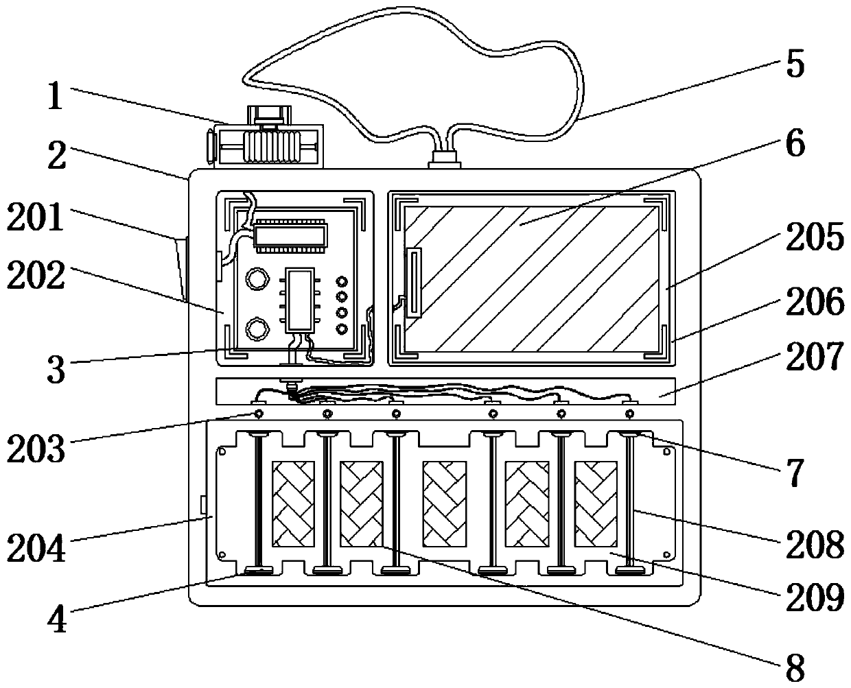
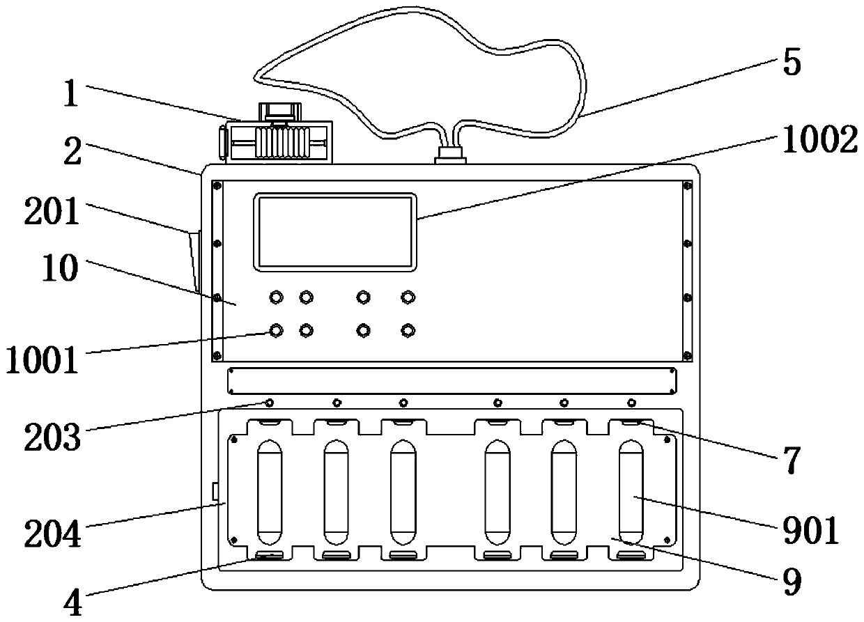
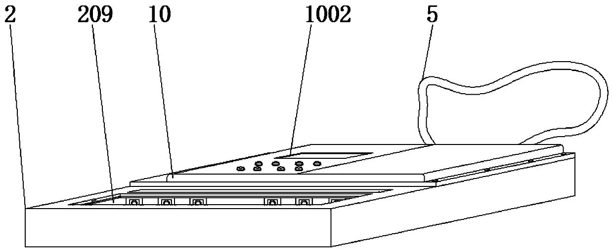
The invention discloses a wireless battery charger, which comprises a mounting cavity and a shell. A first mounting groove and a third mounting groove are formed in the front surface of the shell. A circuit motherboard is mounted in the first mounting groove in an embedded manner. A storage battery is mounted in the third mounting groove in an embedded manner. A wire passing groove is formed in the front surface of the shell below the circuit motherboard and the storage battery. A second mounting groove is formed in the front surface of the shell below the wire passing groove. A wiring grooveis formed in the front surface of the interior of the second mounting groove. Anode blocks and cathode blocks are fixedly mounted at the bottom and the top of the wiring groove respectively. A sealingplate is fixedly mounted on the front surface of the wiring groove. The storage battery enables the charger to achieve a good charging effect and a good endurance effect. The storage battery avoids or reduces the situation in which the charger cannot be connected with a power source to charge a battery and achieves a short endurance effect, and a worker can conveniently carry the charger to supply power to mobile equipment for endurance when going out.

Description

technical field [0001] The invention relates to the technical field of chargers, in particular to a wireless battery charger. Background technique [0002] Battery charger is an electronic device for charging rechargeable batteries used in electric vehicles, electric tools, video games, notebooks, photovoltaics, digital and small portable electronic devices and electronic appliances. It generally consists of a casing, a power conversion part, a charging detection part, a charging protection part, etc Its output type is pure DC or pulsating DC, which can be divided into wall-plug type and desktop type according to the connection mode, and can be divided into nickel-cadmium battery charger, nickel-metal hydride battery charger, nickel-zinc battery Chargers, lead-acid battery chargers, lithium battery chargers, lithium iron phosphate chargers. [0003] Although the existing patent (publication number: CN108879975A) discloses a wireless battery charger with a wireless control s...

Claims


Application Information

Patent Timeline
Patent Type & Authority Applications(China)
IPC IPC(8): H02J7/00B65H75/38B65H75/44
CPCH02J7/0042B65H75/38B65H75/44
Inventor 李洋
Owner XUZHOU HENGYUAN ELECTRICAL APPLIANCES
Learn More