Self-traction type wire coating robot wire feeding and hanging method and corresponding robot

A robot and self-tracting technology, which is applied in the direction of coating, manipulator, and device for coating liquid on the surface, etc., which can solve the problems of manual climbing and other problems

Active Publication Date: 2020-01-24
ELECTRIC POWER RESEARCH INSTITUTE, CHINA SOUTHERN POWER GRID CO LTD +3
View PDF24 Cites 10 Cited by
  • Summary
  • Abstract
  • Description
  • Claims
  • Application Information

AI Technical Summary

Problems solved by technology

[0004] Based on the above-mentioned problems in the prior art, the present invention provides a self-drawing wire coating robot on-line hanging method and the corresponding robot. Coating module and walking module, and then add a winding traction module on the top of the robot. When hanging the line, first rotate the coating module and walking module to the side of the robot, and then use the unmanned equipment to hang the traction belt on the overhead bare wire. Tighten the traction belt through the winding traction module to hang the robot under the bare overhead wire, and finally control the coating module and the walking module to rotate back to the top of the robot to hang the robot on the overhead bare wire; the method and robot solution provided by the present invention It solves the problem in the prior art that manual climbing is required or that large-scale tools are used to assist in the installation of robots. It has the advantages of high spraying efficiency, safety, and simple auxiliary equipment, and the traction belt and shell are made of insulating materials, which can be used in power failures at the same time. or work without a power outage

Method used


Image

  • Self-traction type wire coating robot wire feeding and hanging method and corresponding robot
  • Self-traction type wire coating robot wire feeding and hanging method and corresponding robot
  • Self-traction type wire coating robot wire feeding and hanging method and corresponding robot

Examples


Embodiment Construction

[0039] The present invention will be further described below in combination with specific embodiments and accompanying drawings.

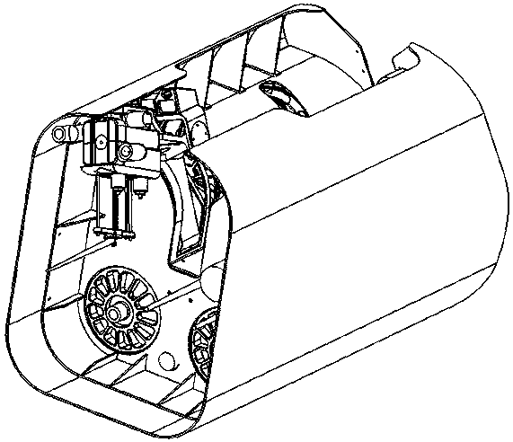
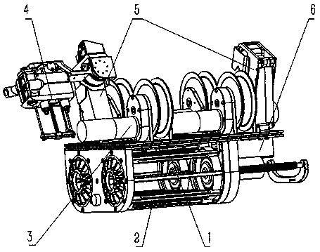
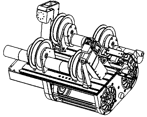
[0040] Such as Figure 1-8 Shown is a self-drawing type wire coating robot on-line hanging method, which is provided on the coating robot with a coating module 4 and a walking module that can automatically take the top of the robot as the axis and rotate toward the extension direction of the non-overhead bare wire 5. Add the reeling traction module 3 on the top of the robot. The power supply and control module 6 is at the end of the robot. Rotate the robot sideways, and then use unmanned equipment such as drones and crawling robots or directly hang the traction belt on the overhead bare wire through a long insulating rod, and tighten the traction belt through the winding traction module 3 to hang the robot on the Under the overhead bare wire, finally control the coating module 4 and the walking module 5 to rotate back to the top of the robot, and ...


PUM


Abstract

The invention provides a self-traction type wire coating robot wire feeding and hanging method and a corresponding robot. The method is characterized in that a coating module and a walking module which can automatically rotate by taking the top of the robot as an axis are arranged on the coating robot, a coiling traction module is added to the top of the robot, during wire hanging, the coating module and the walking module are made to rotate and swing down towards a side edge of the robot, the traction belt is hung on an overhead bare conductor through unmanned equipment, the robot is hung below the overhead bare conductor by tightening the traction belt through the coiling traction module, and finally the coating module and the walking module are controlled for rotating and rising back tothe top of the robot to hang the robot on the overhead bare conductor. The method is advantaged in that a problem that in the prior art, a robot needs to be climbed manually or installed in an auxiliary mode through large tools and instruments is solved, the method is high in spraying operation efficiency, safe, simple in needed auxiliary equipment and the like, the traction belt and a shell aremade of insulating materials, and operation can be conducted under the condition of power failure or no power failure.

Description

technical field [0001] The invention belongs to the field of automatic robots, and in particular relates to a self-drawn wire coating robot used for insulating and spraying overhead bare wires and a wire-on-line-hanging method used by the robot. Background technique [0002] Early overhead power lines were generally in the form of bare wires. Accidentally hanging sundries such as kites and plastic sheets on power lines, and dust on insulators may cause mud flow during storms or heavy rains, which may easily cause short circuits between high-voltage power lines, resulting in unexpected power outages and other accidents. Nowadays, manual spraying is widely used, which has the disadvantages of low efficiency, slow speed, inability to guarantee quality and poor insulation effect. At the same time, it is also prone to accidental poisoning and casualties. [0003] The use of coating robots to spray overhead bare wires has gradually become the main practice in the industry, and t...

Claims


Application Information

Patent Timeline
Patent Type & Authority Applications(China)
IPC IPC(8): H02G1/16B05C5/02B05C11/00B05C11/10B25J11/00
CPCH02G1/16B05C5/0241B05C11/00B05C11/1002B05D7/20B05D1/02B05B15/68H01B13/165B05B13/0436B61B7/06B05C13/00B25J11/0075
Inventor 黄志建张万青赖彬昌
Owner ELECTRIC POWER RESEARCH INSTITUTE, CHINA SOUTHERN POWER GRID CO LTD
Why Eureka
Try Eureka