Device and method for visual experiment of flow trace in rod bundle channel under moving condition

A technology of rod bundle channel and experimental device, which is applied in the field of nuclear power, can solve the problems of deepening the understanding of flow and heat transfer mechanism in the rod bundle channel, and there is no visual experiment device, etc.

Active Publication Date: 2021-05-28
NUCLEAR POWER INSTITUTE OF CHINA
View PDF8 Cites 2 Cited by
  • Summary
  • Abstract
  • Description
  • Claims
  • Application Information

AI Technical Summary

Problems solved by technology

[0004] The object of the present invention is to provide a device and method for visualizing the flow trace in the rod bundle channel under the condition of movement, so as to solve the problem that there is no device suitable for the flow trace visualization experiment in the rod bundle channel under the condition of motion in the prior art. Realize the visualization experiment of single-phase flow traces in the rod bundle channel, obtain the characteristics of the single-phase flow flow trace in the rod bundle channel under different motion conditions, in order to study the influence of motion conditions on the laminar flow and turbulent flow process in the rod bundle channel, and deepen the understanding of Purpose of understanding flow and heat transfer mechanisms in rod bundle channels under moving conditions

Method used


Image

  • Device and method for visual experiment of flow trace in rod bundle channel under moving condition
  • Device and method for visual experiment of flow trace in rod bundle channel under moving condition
  • Device and method for visual experiment of flow trace in rod bundle channel under moving condition

Examples


Embodiment 1

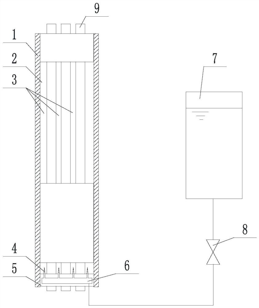
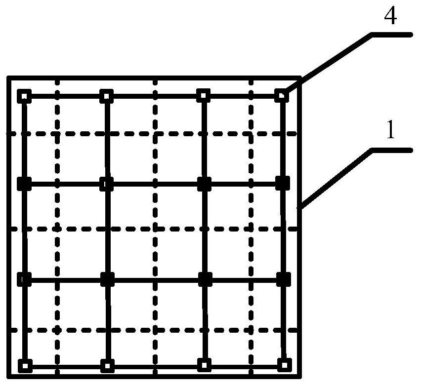
[0033] Such as Figure 1 to Figure 3 The shown experimental device for visualizing the flow path in the rod bundle channel under the condition of movement includes several rod bundle elements 9 and rod bundle channels 3 located in the rod bundle channel shell 1, and the rod bundle channel shell 1 is provided with a visual window 2. The bottom of the rod bundle channel casing 1 is connected to a fixed flange 5, and the fixed flange 5 is used to fix the rod bundle element 9 and enable the working medium to flow into the rod bundle channel 3; the fixed flange 5 Several needles 4 are arranged on the upper surface, and each needle 4 corresponds to a rod bundle channel 3, and a flow channel 6 communicating with all the needles 4 is arranged in the fixed flange 5, and tracer is injected into the flow channel 6. agent injection system.

[0034]Preferably, several openings are provided on the upper surface of the fixed flange 5, and the openings correspond to the rod bundle channels 3...

Embodiment 2

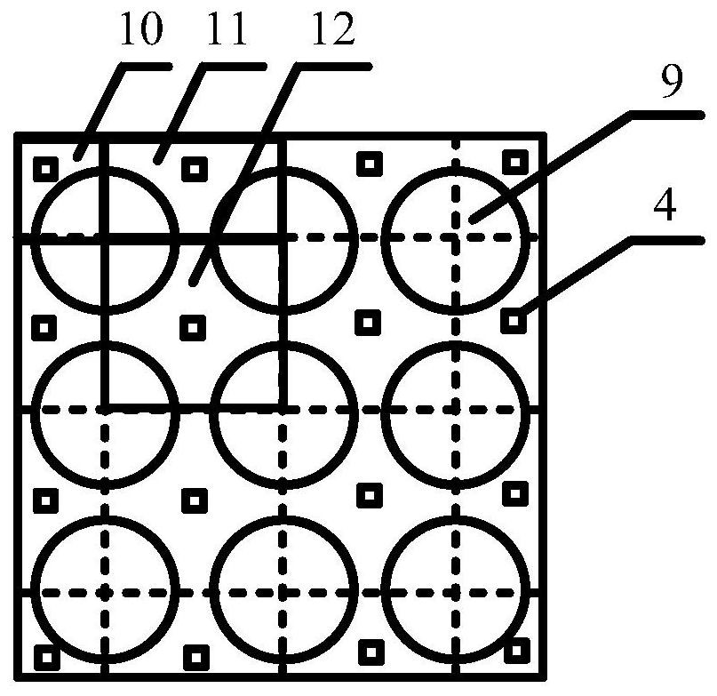
[0039] Such as Figure 1 to Figure 3 Shown is a visual experimental device for the flow trace in the rod bundle channel under the condition of movement. The rod bundle component 9 is assembled in the rod bundle channel shell 1, and a visualization window is set on the side of the shell 1. The rod bundle channel forms an angle channel 10, a side channel 11 and For sub-channel structures of different configurations such as the central channel 12, the fixed flange 5 is installed in the lower part of the bundle channel and connected to the shell 1 of the rod bundle channel, and the upper side of the fixed flange 5 is opened according to the positions of different sub-channels. The needle 4, and the flow channel 6 inside the flange communicates with the opening at the bottom of the flange, and the tracer storage tank 7 is connected through the pipeline, and the valve 8 is set in the pipeline to start or close the injection process, relying on the storage tank and the rod bundle The...

Embodiment 3

[0042] A method for visualizing flow traces in a rod bundle channel under exercise conditions, comprising the following steps:

[0043] (a) inject the tracer into the fixed flange plate 5 at the bottom of the rod bundle passage shell 1 through the injection system;

[0044] (b) The tracer flows from the flow channel 6 in the fixed flange 5 to each needle head 4 connected in parallel, and enters each rod bundle channel 3 through each needle head 4; the tracer entering each rod bundle channel 3 and The working medium is mixed and flows upward together;

[0045] (c) Observing the tracer trace through the viewing window 2 of the housing 1 of the rod bundle channel.

[0046] During the experiment of this embodiment, the working medium flows into the rod bundle channel from the side below the rod bundle channel, and at the same time, the tracer is injected into each rod bundle channel from the fixed flange under the drive of the pump, and the tracer and working fluid On the medium...


PUM


Abstract

The invention discloses an experimental device for visualizing flow traces in a rod bundle channel under moving conditions, which comprises a rod bundle element and a rod bundle channel located in the shell of the rod bundle channel, and a visual window is arranged on the shell of the rod bundle channel; Connect the fixed flange, the fixed flange is used to fix the rod bundle components and enable the working medium to flow into the rod bundle channel; the upper surface of the fixed flange is provided with a number of needles, and the fixed flange is provided with a flow channel connected to all the needles. The channel also includes an injection system for injecting the tracer into the channel. The invention is used to solve the problem in the prior art that there is no device suitable for the flow track visualization experiment in the rod bundle channel under the condition of movement, realize the visualization experiment of the single-phase flow flow track in the rod bundle channel, and obtain the rod bundle under different moving conditions The characteristics of the single-phase flow path in the channel, in order to study the influence of motion conditions on the laminar flow and turbulent flow process in the rod bundle channel, and to deepen the understanding of the flow and heat transfer mechanism in the rod bundle channel under the motion condition.

Description

technical field [0001] The invention relates to the field of nuclear power, in particular to an experimental device and method for visualizing flow traces in a rod bundle channel under moving conditions. Background technique [0002] Floating nuclear power plants and ships are affected by wind and waves during navigation, so that the flow of working fluid in the system is in motion conditions such as swinging and diving. At this time, the single-phase flow system is always affected by tangential force, centrifugal force, and Coriolis force caused by motion conditions. The combined effect of these additional transient external force fields changes the heat transfer law of the single-phase flow in the channel and the flow characteristics of the gas-water two-phase flow, which in turn affects the safety and economy of the nuclear power plant. Therefore, the research on the flow path characteristics and transformation of single-phase flow under the condition of motion has import...

Claims


Application Information

Patent Timeline
Patent Type & Authority Patents(China)
IPC IPC(8): G21C17/00
CPCG21C17/001Y02E30/30
Inventor 鲍伟徐建军黄彦平
Owner NUCLEAR POWER INSTITUTE OF CHINA
Why Eureka
Try Eureka