
display device

A display device and display area technology, which is applied to instruments, computing, electrical and digital data processing, etc., can solve problems such as screen failure, quality inspection and damage in the hole-drilling area, and achieve the effect of improving product yield.

Active Publication Date: 2021-12-03
WUHAN CHINA STAR OPTOELECTRONICS SEMICON DISPLAY TECH CO LTD
View PDF5 Cites 0 Cited by
  • Summary
  • Abstract
  • Description
  • Claims
  • Application Information

AI Technical Summary

Problems solved by technology

However, destructive defects such as damage and cracks may occur in the hole-digging area, resulting in screen failure. If it directly enters the subsequent process, it will affect the product yield
[0003] Therefore, the existing display panel has the technical problem that the quality of the hole-digging area needs to be detected, and needs to be improved.

Method used


Image

  • display device
  • display device
  • display device

Examples


Embodiment Construction

[0031] The following descriptions of the various embodiments refer to the accompanying drawings to illustrate specific embodiments in which the invention may be practiced. The directional terms mentioned in the present invention, such as [top], [bottom], [front], [back], [left], [right], [inside], [outside], [side], etc., are only for reference The orientation of the attached schema. Therefore, the directional terms used are used to illustrate and understand the present invention, but not to limit the present invention. In the figures, elements with similar structures are denoted by the same reference numerals.

[0032] The invention provides a display device to alleviate the technical problem that the quality of the hole-digging area needs to be detected in the existing display panel.

[0033] The display device of the present invention includes a display panel, a touch layer, a detection circuit, and a connection line. The display panel includes a display area and an elect...


PUM


Abstract

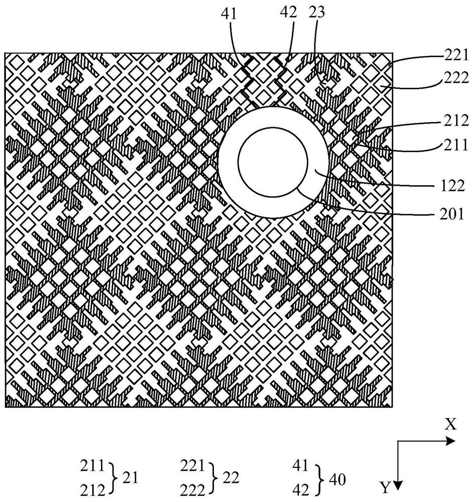
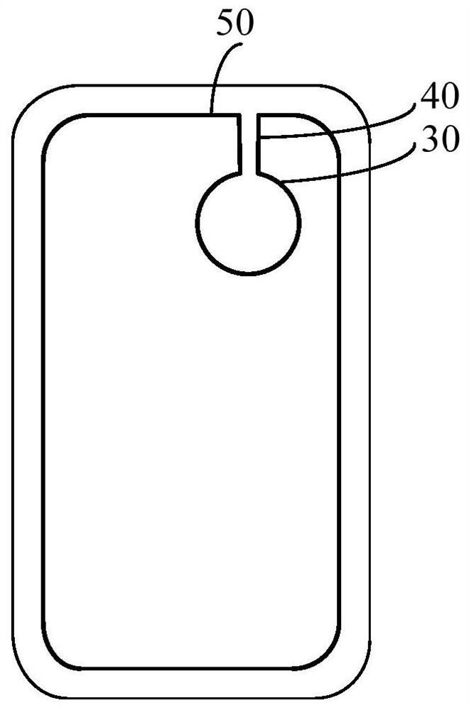
The present invention provides a display device, including a display panel, a touch layer, a detection circuit and connecting wires. The display panel includes a display area and an electronic component installation area corresponding to the electronic component installation position. The electronic component installation area includes a first through hole and A buffer zone, the buffer zone surrounds the first through hole and is in contact with the display area; the touch layer is formed with a touch electrode, and the touch layer is formed with a second through hole in the area corresponding to the first through hole; the detection circuit is arranged in the buffer area The area is used to detect the quality of the first through hole in the display panel; the connection line is formed in the touch layer and used to connect the detection circuit and the peripheral circuit. By designing a detection circuit that introduces the peripheral circuit into the interior from the touch layer, the quality of the hole-digging part of the display panel is inspected, and the damage and cracks at the hole-digging part can be detected in time to avoid the failure of the display device from entering the display panel. Subsequent process flow improves product yield.

Description

technical field [0001] The present invention relates to the field of display technology, in particular to a display device. Background technique [0002] With the development of full-screen technology, it is a development trend to place electronic components such as cameras under the screen under the display screen, and the corresponding display screen needs to be designed with holes. However, destructive defects such as breakage and cracks may occur in the hole-digging area, resulting in screen failure. If it directly enters the subsequent process, it will affect the product yield. [0003] Therefore, the existing display panel has the technical problem that the quality of the hole-digging area needs to be detected, which needs to be improved. Contents of the invention [0004] The invention provides a display device to alleviate the existing technical problem that the quality of the hole-digging area needs to be detected. [0005] In order to solve the above problems, ...

Claims


Application Information

Patent Timeline
Patent Type & Authority Patents(China)
IPC IPC(8): G06F3/041G06F3/044
CPCG06F3/041G06F3/044G06F3/0412G06F3/04164G06F3/0446G06F3/0448G06F2203/04111
Inventor 邓义超叶剑
Owner WUHAN CHINA STAR OPTOELECTRONICS SEMICON DISPLAY TECH CO LTD
Learn More