Air conditioner indoor unit
An air conditioner indoor unit and volute technology, which is used in air conditioning systems, space heating and ventilation, household heating, etc., can solve the problem of reducing the overall performance of the air conditioner, uneven air output at the joint of the air duct, and affecting the aerodynamic performance of the fan blades. and other problems, to achieve the effect of improving the uneven air outlet, avoiding the loss of air volume, and preventing the return air.
- Summary
- Abstract
- Description
- Claims
- Application Information
AI Technical Summary
Problems solved by technology
Method used
Image
Examples
Embodiment 1
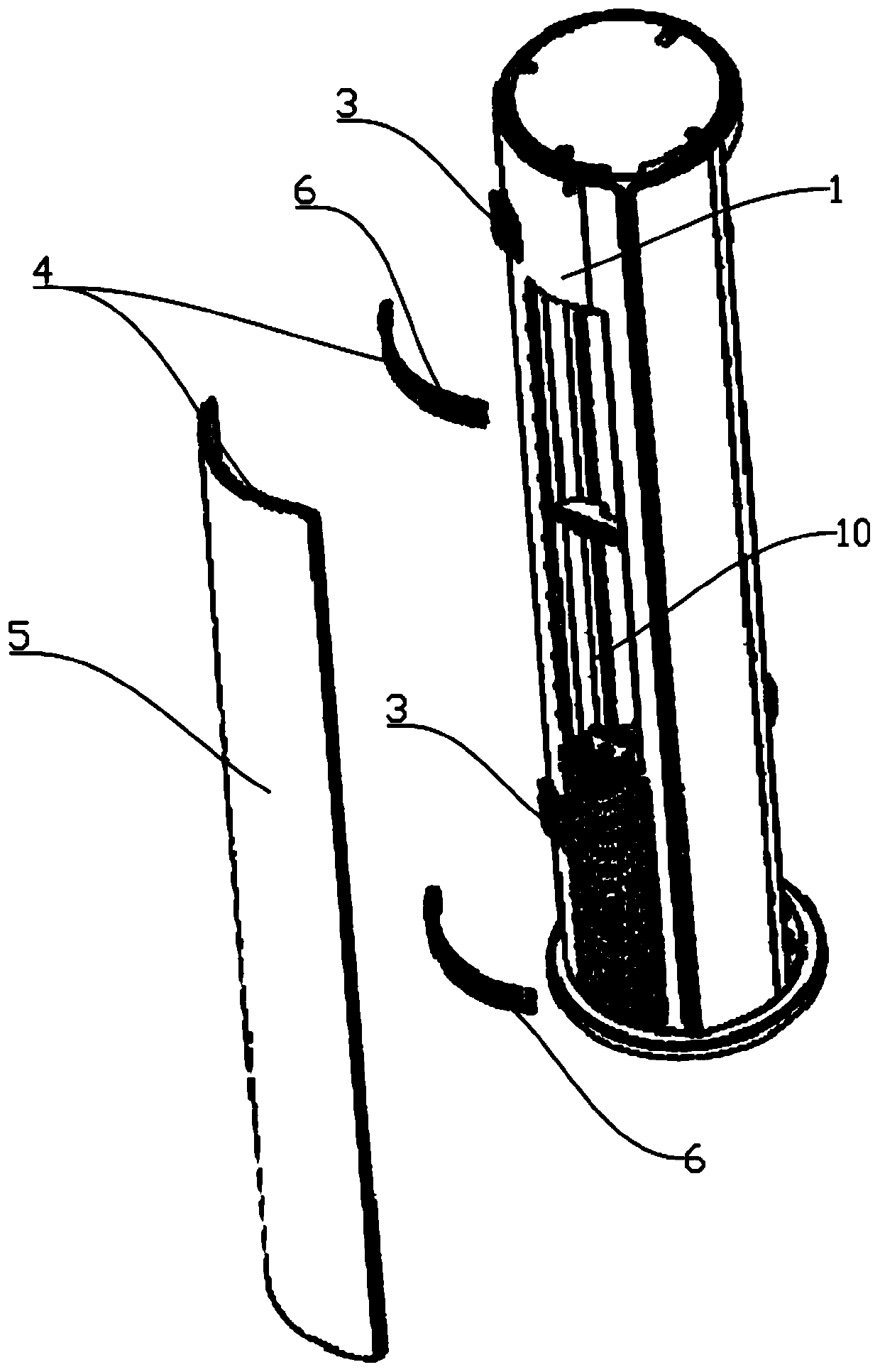
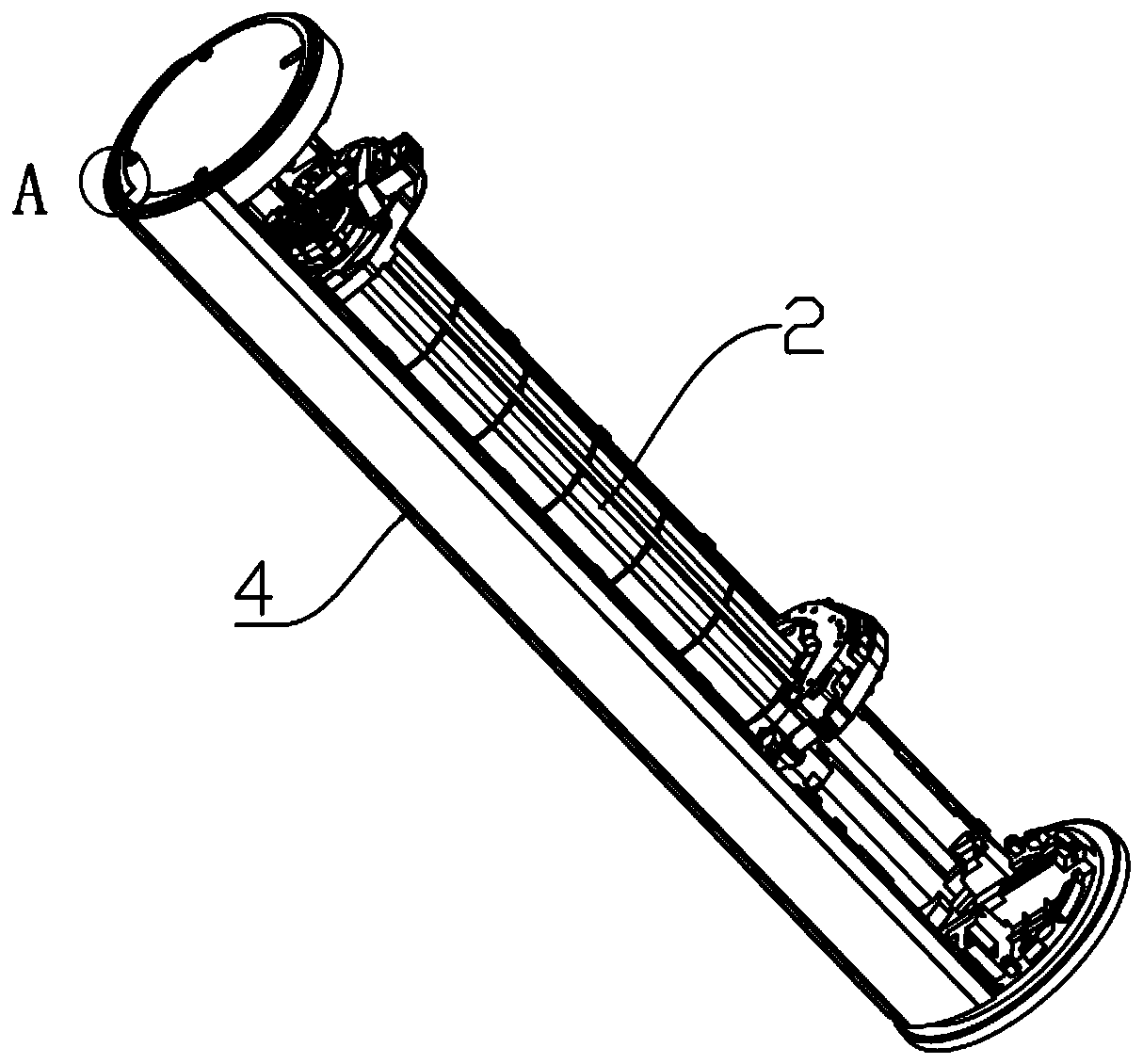
[0061] An air conditioner indoor unit, such as Figure 1-Figure 7 As shown, the air conditioner indoor unit includes a casing, the front of the casing is combined with a front panel 1, and the front panel 1 is provided with an air outlet 10; the casing is provided with an air inlet; the casing A volute 2 is arranged inside, and a fan is arranged inside the volute 2, and a heat exchanger is arranged between the fan and the air inlet. Under the action of the fan, the air enters through the air inlet and passes through the heat exchanger; the air passing through the heat exchanger is discharged into the room through the air outlet 10 through the fan.
[0062] The casing is provided with a driving mechanism 3 and a sliding door assembly 4; the driving mechanism 3 drives the sliding door assembly 4 to slide relative to the front panel 1 in the peripheral direction, thereby opening or closing the air outlet 10 on the front panel 1.
[0063] like figure 1 As shown, the sliding door...
Embodiment 2
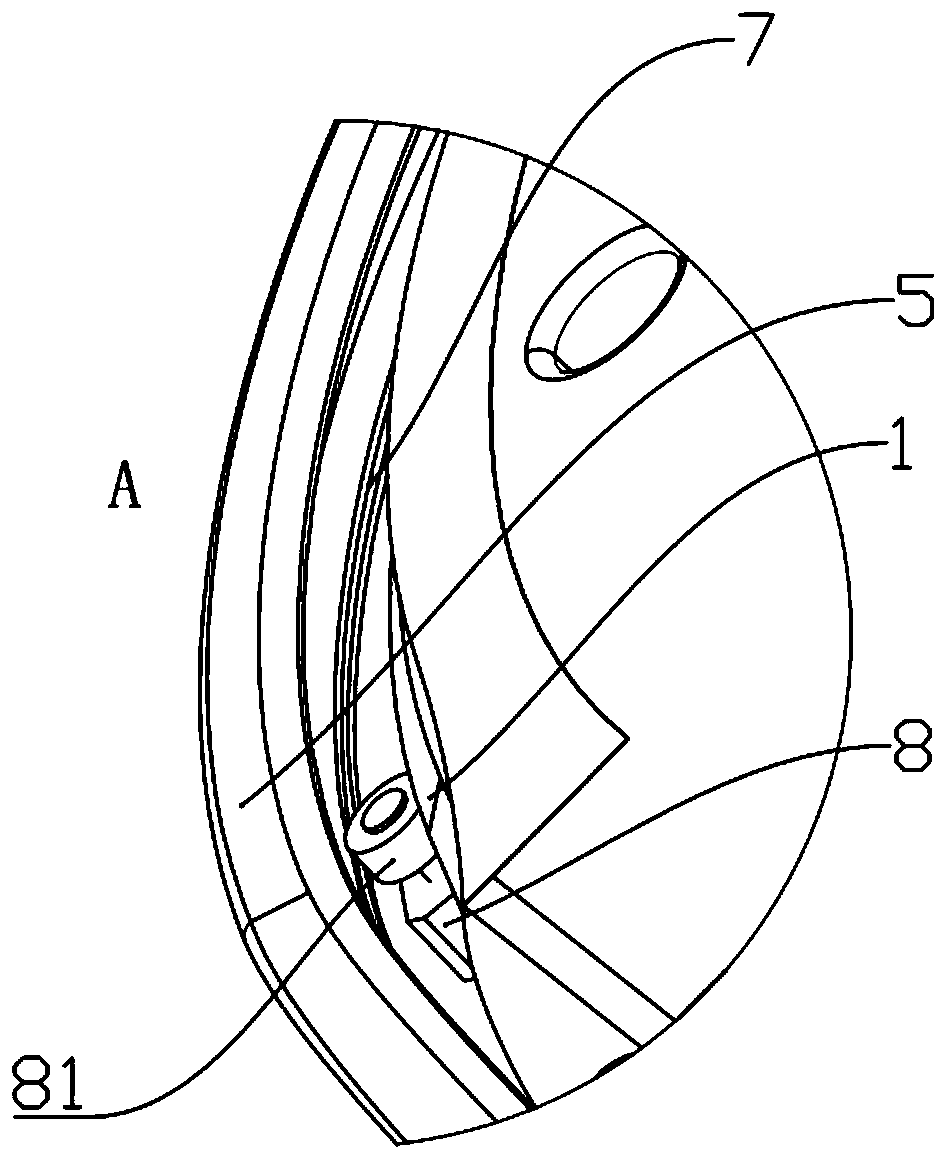
[0075] The principle of this embodiment is the same as that of Embodiment 1, and the difference is that: when the sliding door 5 operates normally, there is a distance between the roller 81 and the guide bar 7, that is, the sliding door assembly 4 (the sliding door 5 or the teeth When the bar 6) does not deform, there is a distance between the roller 81 and the guide bar 7.
[0076] In this embodiment, under the normal operation of the sliding door 5, there is a distance between the roller 81 and the guide bar 7, that is, the rolling assembly 8 does not come into contact with the sliding door assembly 4 (sliding door 5 or rack 6). , at this time the sliding door 5 can slide stably relative to the front panel 1 to selectively open or close the opening.
[0077] In addition, when the sliding door assembly 4 (sliding door 5 or rack 6) is deformed under special circumstances, it can be supported by the roller 81 on the guide bar 7 on the sliding door assembly 4 (sliding door 5 or ...
Embodiment 3
[0080] This embodiment mainly describes the reinforcement structure of the sliding door 5 . Its principle is the same as that of embodiment one and embodiment two, and its main difference is: as Figure 8-Figure 26 As shown, the sliding door 5 is provided with a mounting groove 51 on the inner side close to the front panel 1 , and the overall curvature of the mounting groove 51 is consistent with that of the sliding door 5 ; a reinforcing member 52 is provided in the mounting groove 51 . In this embodiment, the reinforcing member 52 is set as a plastic member, which can effectively strengthen the lateral strength of the sliding door 5 . Vertically, the inside of the sliding door 5 is provided with a plurality of installation grooves 51 arranged side by side, which effectively enhances the overall strength of the sliding door 5 .
[0081] The installation groove 51 includes a base plate 511, and the plane of the sliding door 5 is perpendicular to the base plate 511; the base p...
PUM
 Abstract
Description
Claims
Application Information
 - Generate Ideas
- Intellectual Property
- Life Sciences
- Materials
- Tech Scout
- Unparalleled Data Quality
- Higher Quality Content
- 60% Fewer Hallucinations
Browse by: Latest US Patents, China's latest patents, Technical Efficacy Thesaurus, Application Domain, Technology Topic, Popular Technical Reports.
© 2025 PatSnap. All rights reserved.Legal|Privacy policy|Modern Slavery Act Transparency Statement|Sitemap|About US| Contact US: help@patsnap.com


