Slurry circulating slag discharging system for shaft heading machine

The technology of roadheader and mud is applied in the field of mud circulating slag system for shaft roadheader, which can solve problems such as hidden safety hazards, slag overturning, wire cable breakage, etc., and achieves reduced labor intensity, improved construction environment, and good adaptability. Effect

Pending Publication Date: 2020-01-24
CHINA RAILWAY CONSTR HEAVY IND
View PDF1 Cites 2 Cited by
  • Summary
  • Abstract
  • Description
  • Claims
  • Application Information

AI Technical Summary

Problems solved by technology

During the long-distance lifting of the muck, the cable breakage and the overturning of the muck that may occur in the long-distance lifting process also make this construction method have greater safety hazards

Method used


Image

  • Slurry circulating slag discharging system for shaft heading machine

Examples


Embodiment 1

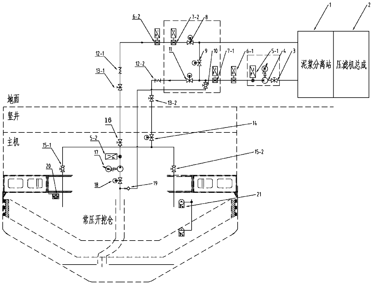
[0034] see figure 1 , a mud circulation and slag discharge system for a shaft boring machine, comprising a slurry inlet pipeline, a slurry discharge pipeline, a flushing pipeline, a bypass pipeline and a mud treatment device, one end of the slurry inlet pipeline is connected to the mud treatment device, and the other One end is set in the excavation bin of the roadheader to transport the slurry treated by the mud treatment device to the excavation bin. The slurry pipeline transports the slurry in the excavation bin to the mud treatment device, and realizes the circulation of the slurry between the excavation bin and the mud treatment device through the slurry inlet pipeline and the slurry discharge pipeline;

[0035] The flushing pipeline is connected to the slurry inlet pipeline and the slurry discharge pipeline located at the slurry discharge port in the excavation bin, and the slurry discharge port is dredged through the flush pipeline, and the bypass pipeline is connected ...


PUM


Abstract

The invention provides a slurry circulating slag discharging system for a shaft heading machine, The system comprises a slurry inlet pipeline, a slurry discharge pipeline, a flushing pipeline, a bypass pipeline and a slurry treatment device, wherein one end of the slurry inlet pipeline is connected with the slurry treatment device, the other end of the slurry inlet pipeline is arranged in an excavation bin of the heading machine, slurry treated by the slurry treatment device is conveyed into the excavation bin, one end of the slurry discharge pipeline is arranged in the excavation bin, the other end of the slurry discharge pipeline is connected with the slurry treatment device, the slurry in the excavation bin is conveyed to the slurry treatment device through the slurry discharge pipeline, the flushing pipeline is connected with slurry discharge ports, located in the excavation bin, of the slurry inlet pipeline and the slurry discharge pipeline, the slurry discharge ports are dredgedthrough the flushing pipeline, the bypass pipeline is connected with the slurry inlet pipeline and the slurry discharge pipeline, and a slurry conveying cycle is formed between the slurry inlet pipeline, the bypass pipeline, the slurry discharge pipeline and the slurry treatment device. The slurry circulating slag discharging system integrates circulating slag discharging and slurry discharge portdredging functions, and the bypass pipeline is arranged to facilitate maintenance of the system.

Description

technical field [0001] The invention relates to the technical field of roadheaders, in particular to a mud circulation and slag discharge system for a shaft roadheader. Background technique [0002] With the development of today's science and technology, people's development and utilization of underground space resources are becoming more and more extensive. In underground engineering, roadheaders are favored by various construction units because of their high construction efficiency, high safety and comfortable working environment. At present, shafts of different sizes need to be excavated in many fields such as underground engineering, mineral mining, municipal water conservancy, civil air defense and military affairs, so the development of shaft boring machine technology has attracted widespread attention. Shaft excavation is different from conventional horizontal excavation. It is impossible to use screw conveyors combined with belt conveyors for continuous slag removal...

Claims


Application Information

Patent Timeline
Patent Type & Authority Applications(China)
IPC IPC(8): E21D1/00E21D9/12
CPCE21D1/00E21D9/12
Inventor 刘飞香文中保刘在政易格陈兴朱颖智
Owner CHINA RAILWAY CONSTR HEAVY IND
Why Eureka
Try Eureka