
Vacuum chuck device and robot

A technology of vacuum suction cups and suction cups, applied in the field of robotics, can solve problems such as inability to achieve miniaturization, mismatching power requirements, and large volume of composite robots

Pending Publication Date: 2020-01-24
南京极智嘉机器人有限公司
View PDF0 Cites 4 Cited by
  • Summary
  • Abstract
  • Description
  • Claims
  • Application Information

AI Technical Summary

Problems solved by technology

However, the existing air compressors are mainly powered by AC power supply, while other components of the composite robot are mainly powered by DC power supply. Due to the mismatch of power requirements between the two, it not only makes the power supply and use of the composite robot more difficult. , and lead to the large volume of existing composite robots, which cannot be miniaturized

Method used


Image

  • Vacuum chuck device and robot
  • Vacuum chuck device and robot

Examples


Embodiment Construction

[0030] The technical solutions of the present invention will be clearly and completely described below in conjunction with the accompanying drawings. Apparently, the described embodiments are some of the embodiments of the present invention, but not all of them. Based on the embodiments of the present invention, all other embodiments obtained by persons of ordinary skill in the art without making creative efforts belong to the protection scope of the present invention.

[0031] In the description of the present invention, it should be noted that the terms "center", "upper", "lower", "left", "right", "vertical", "horizontal", "inner", "outer" etc. The indicated orientation or positional relationship is based on the orientation or positional relationship shown in the drawings, and is only for the convenience of describing the present invention and simplifying the description, rather than indicating or implying that the referred device or element must have a specific orientation, ...


PUM


Abstract

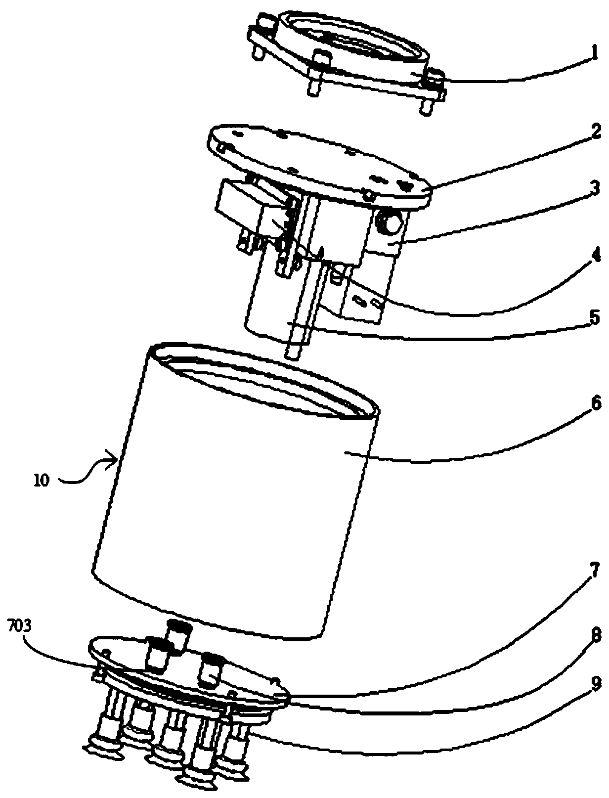
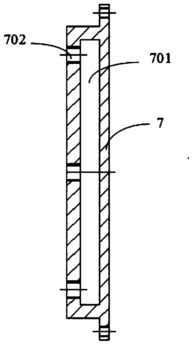
The invention discloses a vacuum chuck device and a robot, and belongs to the technical field of robots. The vacuum chuck device comprises a chuck mounting base, a relay, a vacuum chuck assembly and an electric vacuum breaking valve, wherein the vacuum chuck assembly comprises a vacuum pump and a vacuum chuck; the relay, the vacuum pump and the electric vacuum breaking valve are arranged inside the chuck mounting base; the relay is used for being externally connected with a direct-current power supply and a control mechanism; the vacuum pump and the electric vacuum breaking valve are electrically connected with the relay; when the electric vacuum breaking valve is configured to be opened, the vacuum chuck communicates with the outside atmosphere; and when the electric vacuum breaking valveis configured to be closed, the vacuum chuck adsorbs a to-be-adsorbed part under the action of the vacuum pump. According to the vacuum chuck device, an alternating-current power supply does not needto be used, and grabbing operation of the to-be-adsorbed part can be realized only under the driving of the direct-current power supply, so that the vacuum chuck device is low in power supply difficulty, simple in structure and beneficial to realizing miniaturization.

Description

technical field [0001] The invention relates to the technical field of robots, in particular to a vacuum chuck device and a robot. Background technique [0002] With the extensive application of composite robots formed by automatic guided transport vehicles and robotic arms in various industries, the existing composite robots are developing towards small size, light weight and ease of use. Traditional composite robots mainly use a vacuum gripping solution including an air compressor, a vacuum generator, and a vacuum suction cup to realize the gripping operation of the robotic arm. However, the existing air compressors are mainly powered by AC power supply, while other components of the composite robot are mainly powered by DC power supply. Due to the mismatch of power requirements between the two, it not only makes the power supply and use of the composite robot more difficult. , and lead to the large size of the existing composite robot, which cannot be miniaturized. [0...

Claims


Application Information

Patent Timeline
IPC IPC(8): B25J15/06
CPCB25J15/06B25J15/0616
Inventor 闫杰
Owner 南京极智嘉机器人有限公司
Learn More