
Optical network unit equipment

A technology for optical network units and equipment, applied in electrical components, data exchange details, selection devices for multiplexing systems, etc., can solve the problems of inability to adapt to the application environment, troublesome power supply, low power supply flexibility, etc. Flexibility and reliability of safe power supply, reducing power supply difficulty, and cost-saving effects

Active Publication Date: 2012-12-05
北京格林伟迪科技股份有限公司 +1
View PDF0 Cites 0 Cited by
  • Summary
  • Abstract
  • Description
  • Claims
  • Application Information

AI Technical Summary

Problems solved by technology

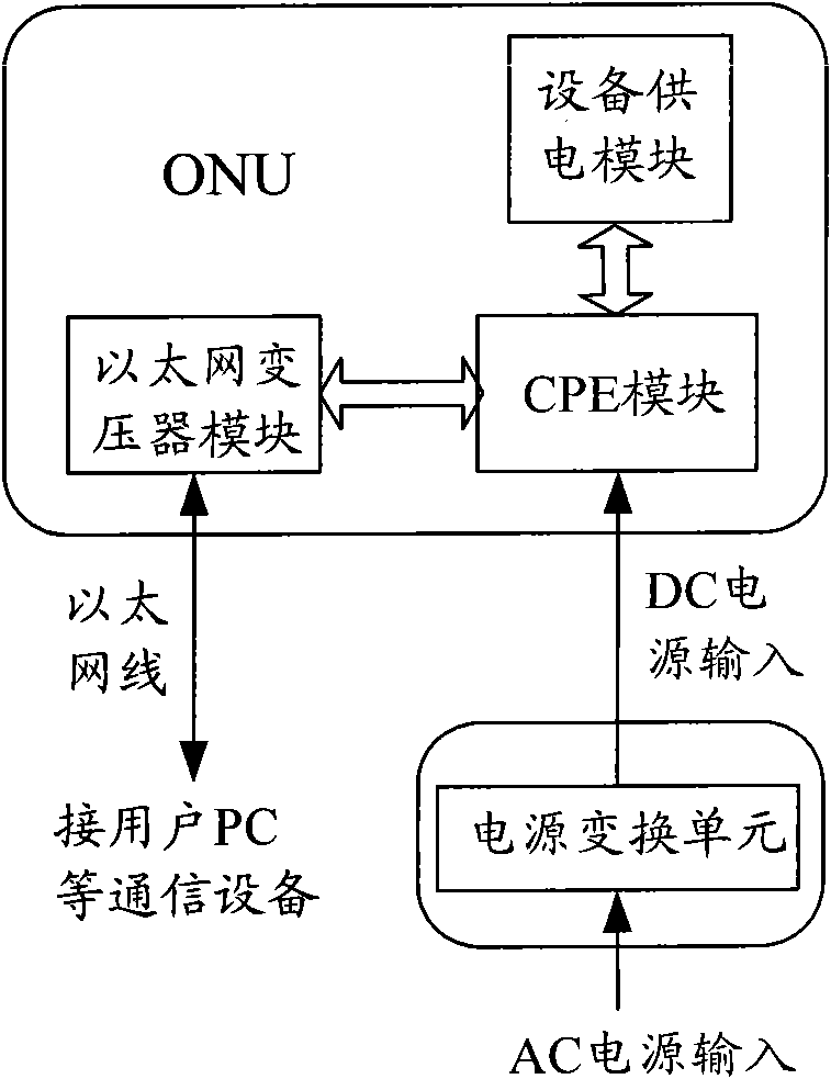
For the situation where the desktop is deployed in the user's study, the ONU device can directly obtain the power supply voltage from AC 220V, and the AC 220V voltage signal is output to the CPE modules in the ONU through the power conversion unit; In the case of deployment, it is often because there is no AC 220V power supply in the weak current box, and it is necessary to connect the AC 220V power supply at the desk of the study to the power conversion unit through the power cable, which causes trouble for the power supply of the ONU equipment, and the power supply flexibility is low and cannot adapt to different The application environment; at the same time, the use of power lines is also prone to safety hazards, and the reliability of safe power supply is low

Method used


Image

  • Optical network unit equipment
  • Optical network unit equipment
  • Optical network unit equipment

Examples


Embodiment Construction

[0042] In order to make the object, technical solution and advantages of the present invention clearer, the present invention will be further described in detail below with reference to the accompanying drawings and examples.

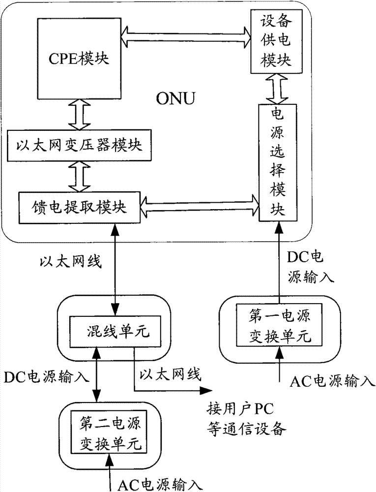
[0043] In practical applications, for the Ethernet cable in the ONU device, it is used to transmit the data interacted between the user and the network. If the ONU device is placed in the weak current box reserved in the user's wall, the Ethernet cable in the ONU device It is connected to the desktop communication equipment in the user's study such as a PC through the pre-set channel in the wall. Therefore, in the embodiment of the present invention, consider using the channel reserved for the Ethernet cable in the wall, so that the reliability of safe power supply can be improved.

[0044] Further, considering the use characteristics of existing Ethernet cables: existing Ethernet cables generally have four pairs of twisted wires, wherein only two pairs ...


PUM


Abstract

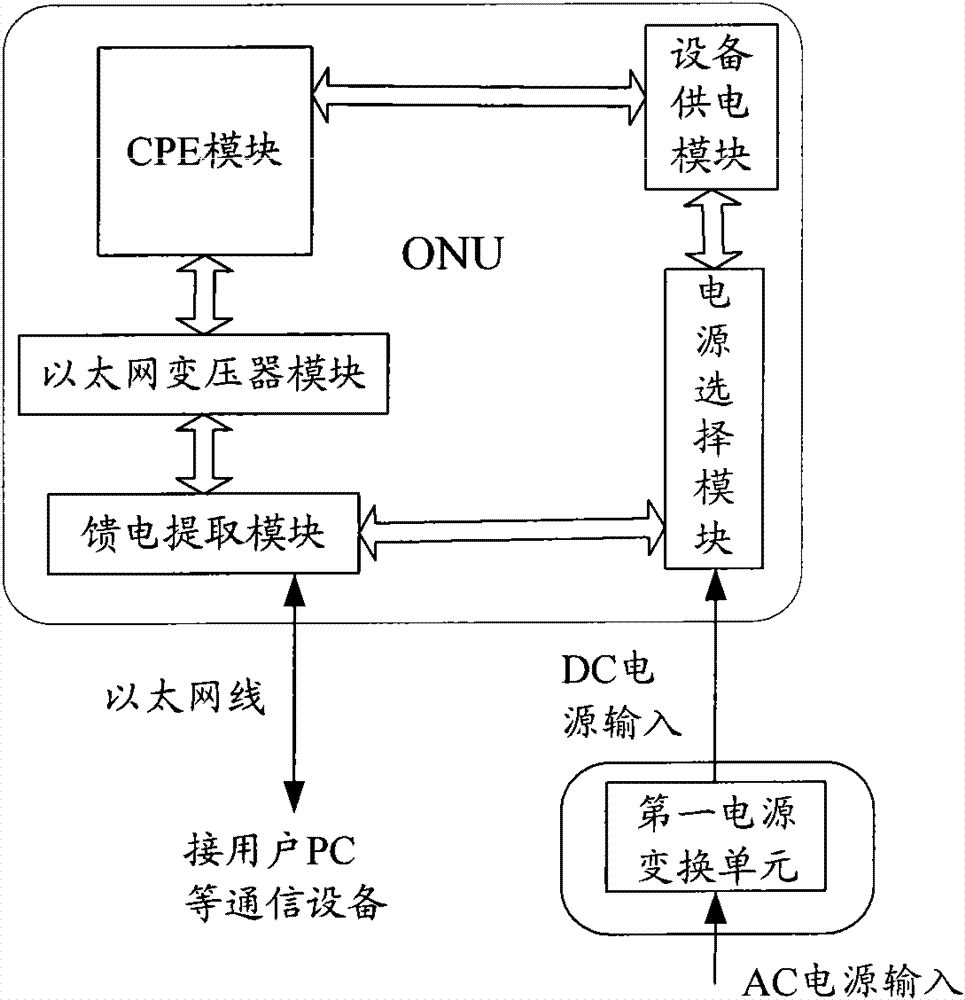
The invention discloses optical network unit equipment, which comprises a first power conversion unit, a second power conversion unit, a swinging cross unit and an ONU, wherein the first power conversion unit is electrically connected with an external AC power supply to convert an inputted AC voltage signal into an operating voltage needed by the ONU and then to output the operating voltage to the ONU; the second power conversion unit is used for inputting the AC voltage signal from the input end of the external AC power supply, converting the AC voltage signal into the operating voltage needed by the ONU and outputting the operating voltage to the swinging cross unit; the swinging cross unit is used for receiving an operating voltage signal which is outputted by the second power conversion unit and is needed by the ONU, loading the operating voltage signal on a pair of stranded wires which are arranged redundantly in an Ethernet cable and outputting the operating voltage signal to the ONU with a data signal from a user; and the ONU is used for receiving a signal transmitted by the swinging cross unit through the Ethernet cable to separate the operating voltage signal needed by the ONU, and receiving the operating voltage which is inputted by the first power conversion unit and needed by the ONU and selecting a direct-current voltage needed by one path of ONU to supply power to each module in the ONU. By applying the optical network unit equipment, the power supply flexibility and safe power distribution reliability can be improved.

Description

technical field [0001] The invention relates to an optical network power supply technology, in particular to an optical network unit device. Background technique [0002] With the accelerated pace of triple play, the network terminal Passive Optical Network (PON, Passive Optical Network) plays an increasingly important role in the optical access network. As users have higher and higher requirements for service bandwidth and service quality, PON nodes are gradually moving down. At present, operators at home and abroad are already deploying fiber-to-the-home (FTTH, Fiber To The Home) technical solutions, that is, fiber-to-the-home , to provide a variety of businesses and services. The PON system consists of an Optical Network Unit (ONU, Optical Network Unit), an Optical Line Terminal (OLT, Optical Line Terminal), and an Optical Distribution Network (ODN, Optical Distribution Network). [0003] In the FTTH technical solution, the ONU is placed in the user's home and can provi...

Claims


Application Information

Patent Timeline
Patent Type & Authority Patents(China)
IPC IPC(8): H04Q11/00H04L12/10
Inventor 盖鹏飞汪德煌邓羽刘春艳
Owner 北京格林伟迪科技股份有限公司
Learn More