
Multi-liquid-chamber annular hydraulic torsional vibration damper

A technology of torsional vibration damper and liquid chamber, which is applied in the direction of shock absorber, shock absorber-spring combination, shock absorber, etc., can solve the problems of insufficient vibration damping performance, complex structure, unsatisfactory and other problems, and achieve the overall cost Low, eliminates dynamic hardening, dampening effect of torsional vibration

Inactive Publication Date: 2020-01-21
JILIN UNIV
View PDF8 Cites 0 Cited by
  • Summary
  • Abstract
  • Description
  • Claims
  • Application Information

AI Technical Summary

Problems solved by technology

[0004] In order to solve the problem that the existing torsional vibration damper has insufficient vibration damping performance, complex structure, high cost, and cannot meet the requirements of the complex working conditions of transmission system vibration damping, the present invention provides a multi-liquid chamber annular hydraulic torsion Vibration shock absorber, using the good vibration isolation performance and cost advantages of the hydraulic structure, combined with the hydraulic vibration damping structure, taking into account the vibration isolation of the low-frequency large amplitude and high-frequency small amplitude of the transmission system, to meet the complex torsional vibration conditions of the automobile transmission system vibration damping requirements, and can be further applied to vibration damping of drive shafts and other power transmission systems of automobiles

Method used


Image

  • Multi-liquid-chamber annular hydraulic torsional vibration damper
  • Multi-liquid-chamber annular hydraulic torsional vibration damper
  • Multi-liquid-chamber annular hydraulic torsional vibration damper

Examples


Embodiment Construction

[0035] The technical solution of the present invention will be described in detail below in conjunction with the drawings:

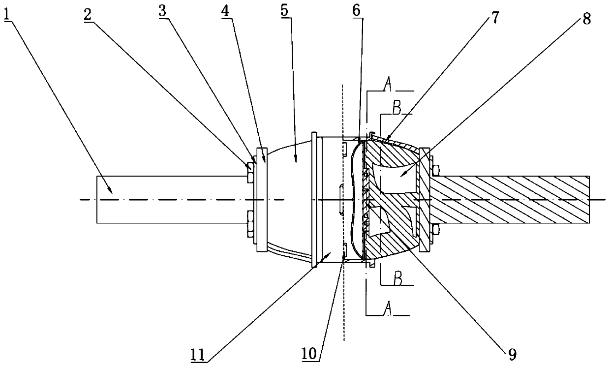
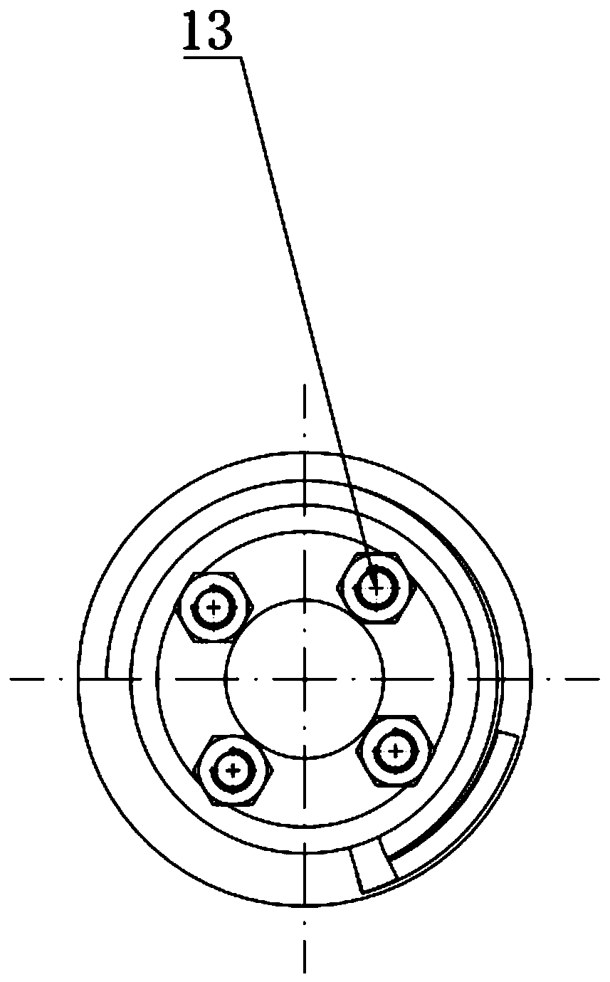
[0036] Such as Figure 1 to Figure 6 As shown, a multi-liquid annular hydraulic torsional vibration damper includes: a rubber fixing plate 4 connected to the shaft end of the left engine crankshaft 1 through a flange 3, and a left rubber liquid connected to the rubber fixing plate 4 Chamber 5, the housing 11 connected to the other end of the rubber liquid chamber 5, the right rubber liquid chamber connected to the other end of the housing, the rubber fixing plate connected to the other end of the right rubber liquid chamber, the rubber fixing plate passes through the flange Connect with the crankshaft end of the right engine. After the rubber liquid chambers 5 on the left and right sides are connected with the housing 11, the whole structure is mirror-symmetrical with respect to the axial center surface of the housing 11. Inertial channels 9 are provided b...


PUM


Abstract

The invention discloses a multi-liquid-chamber annular hydraulic torsional vibration damper. Vibration damping needs under the complex torsional vibration working condition of a car transmission system can be met, and the damper comprises a rubber fixed plate connected with the end of an engine crankshaft on the left side through a flange disc, a left side rubber liquid chamber connected with therubber fixed plate, a shell connected with the other end of the rubber liquid chamber, a right side rubber liquid chamber connected with the other end of the shell, and a rubber fixed plate connectedwith the other end of the right side rubber liquid chamber. The rubber fixed plate is connected with the end of an engine crankshaft on the right side through a flange disc, inertia channels are arranged between the two ends of the shell and the left and right rubber liquid chambers, two rubber films communicating with the inertia channels on the corresponding sides are arranged in the shell, multiple rubber small liquid chambers are evenly arranged in the rubber liquid chambers with the rotation axis lines as the axes, each rubber small liquid chamber communicates with the corresponding inertia channel, the rubber small liquid chambers, the inertia channels and the rubber films form multiple fluid circulation systems, and the rubber fixed plates, the rubber liquid chambers, the inertia channels and the shell share the corotational axis.

Description

Technical field [0001] The invention relates to a transmission shock absorption damping component on an automobile, in particular to a multi-fluid chamber annular hydraulic torsional vibration damper. Background technique [0002] During the working process of a piston engine, the vibration generated by the deflagration will be transmitted to the crankshaft through the piston connecting rod, causing the instantaneous angular velocity of the crankshaft to change. This change will affect the vibration of the engine crankshaft and subsequent parts connected with the crankshaft. [0003] In order to reduce the vibration to a reasonable range, existing engines are equipped with torsional vibration damper on the free end of the crankshaft. Generally, the existing torsional vibration dampers mostly use rubber-type torsional vibration dampers or silicone oil torsional vibration dampers. Such dampers can be applied to some low-power automotive engines, and cannot be used such as low-speed ...

Claims


Application Information

Patent Timeline
Patent Type & Authority Applications(China)
IPC IPC(8): F16F13/10
CPCF16F13/10F16F2222/12
Inventor 陈志勇高鑫拱超凡赵路洋郑鹏
Owner JILIN UNIV
Learn More