
Arm supporting structure for medical diagnosis and treatment bed

A support structure, technology of diagnosis and treatment bed, applied in the direction of surgery, operating table, medical science, etc., can solve the problems of poor versatility, achieve the effect of convenient implementation, simple structure, and meet the needs of diagnosis and treatment

Pending Publication Date: 2020-01-21
久久艳阳福祉科技(江苏)有限公司
View PDF0 Cites 1 Cited by
  • Summary
  • Abstract
  • Description
  • Claims
  • Application Information

AI Technical Summary

Problems solved by technology

[0004] However, in the adjustment process of the arm, it mainly involves rotating up and down and rotating around the vertical direction (expanding outwards and retracting inwards), so as to meet the needs of patients for diagnosis and treatment. Most of them are set in stages, showing different heights at different positions. In this way, these fixed positions are not necessarily suitable for every patient, so the versatility is poor

Method used


Image

  • Arm supporting structure for medical diagnosis and treatment bed
  • Arm supporting structure for medical diagnosis and treatment bed
  • Arm supporting structure for medical diagnosis and treatment bed

Examples


Embodiment Construction

[0036] In order to make the above-mentioned purpose, features and advantages of the present application more obvious and understandable, the specific implementation manners of the present application will be described in detail below in conjunction with the accompanying drawings. In the following description, numerous specific details are set forth in order to provide a thorough understanding of the application. However, the present application can be implemented in many other ways different from those described here, and those skilled in the art can make similar improvements without departing from the connotation of the present application, so the present application is not limited by the specific embodiments disclosed below.

[0037] In the description of the present application, it should be understood that the terms "center", "longitudinal", "transverse", "length", "width", "thickness", "upper", "lower", "front", " Back", "Left", "Right", "Vertical", "Horizontal", "Top", "...


PUM


Abstract

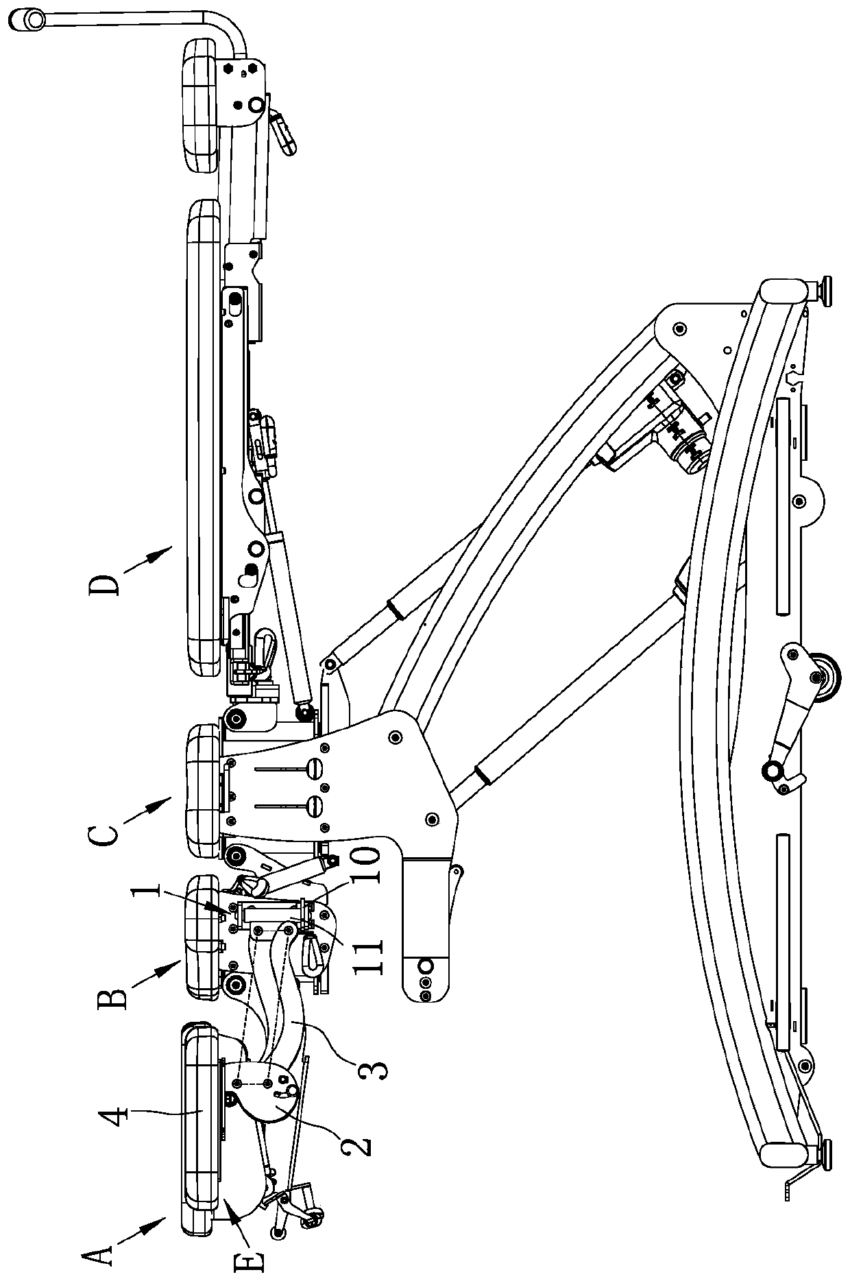
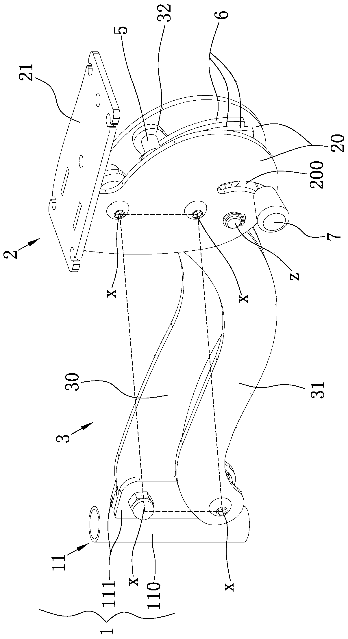
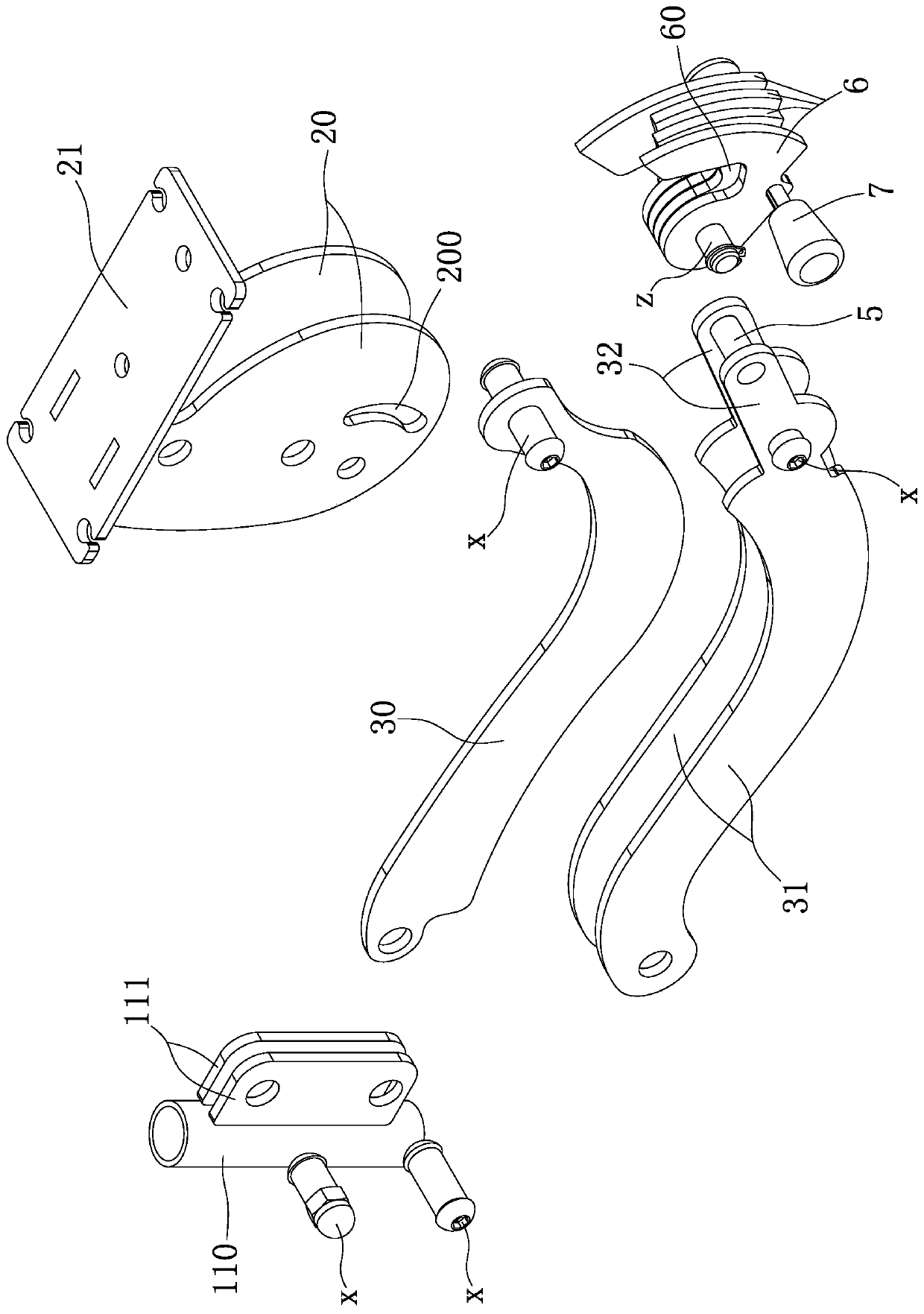
The invention relates to an arm supporting structure for a medical diagnosis and treatment bed. The arm supporting structure comprises a connecting base, an arm base, a connecting brace rod which is used for connecting the connecting base and the arm base, and an arm cushion, wherein the connecting brace rod comprises an upper connecting rod, a lower connecting rod and an extension rod; the upperconnecting rod and the lower connecting rod are separately and rotatably connected with the connecting base and the arm base through a pin shaft from the two end parts and can form a four-connecting-rod mechanism, and the extension rod is arranged on a connecting end part of the lower connecting rod or the upper connecting rod and the arm base; the arm supporting structure also comprises a limiting column which is arranged on the end part of the extension rod and is parallel to the pin shaft and a plurality of limiting supporting pieces which can be arranged on the arm base around a rotating shaft parallel to the limiting column in a rotatable adjusting manner and can form arc supporting faces with different radius. According to the arm supporting structure disclosed by the invention, thearc supporting faces with the different radius is in contact clamping with the limiting columns to ensure that the four-connecting-rod mechanism is locked in different states, and thus, the arm base is positioned on any positions between the highest position and the lowest position, and meanwhile, acting force is applied to the arm base, and the clamping between the limiting supporting pieces andthe limiting column is tighter, a diagnosis and treatment need is further met.

Description

technical field [0001] The invention belongs to the field of medical auxiliary equipment, in particular to an arm support structure of a medical electric diagnosis and treatment bed. Background technique [0002] Medical electric diagnosis and treatment bed is a kind of equipment for patients to lie down. It can also be used for health care, such as common massage. Therefore, it is a common diagnosis and treatment equipment in hospitals, clinics, beauty salons and other places. [0003] At present, in order to facilitate the diagnosis and treatment of patients, doctors and therapists need to perform functions such as multi-angle traction, deflection (or steering), and vibration on the medical electric diagnosis and treatment bed. [0004] However, in the adjustment process of the arm, it mainly involves rotating up and down and rotating around the vertical direction (expanding outwards and retracting inwards), so as to meet the needs of patients for diagnosis and treatment. ...

Claims


Application Information

Patent Timeline
IPC IPC(8): A61G13/08A61G13/12
CPCA61G13/08A61G13/1235
Inventor 陈宇豪周建军
Owner 久久艳阳福祉科技(江苏)有限公司
Learn More