
Cable bushing

A technology for cables and some components, applied in the field of cable lead-throughs, can solve the problems of high sealing and non-allowance, and achieve the effect of high sealing and simple sealing

Active Publication Date: 2020-01-17
ICOTEK PROJEKT
View PDF7 Cites 2 Cited by
  • Summary
  • Abstract
  • Description
  • Claims
  • Application Information

AI Technical Summary

Problems solved by technology

However, since the components are usually only plugged together, they do not allow a high degree of tightness of the system against water and moisture

Method used


Image

  • Cable bushing
  • Cable bushing
  • Cable bushing

Examples


Embodiment Construction

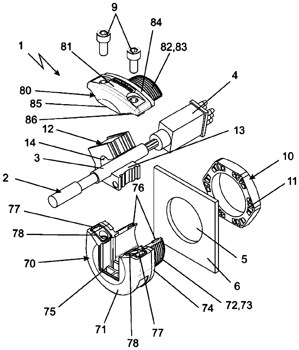
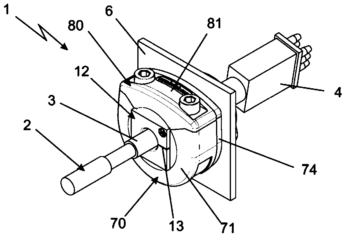
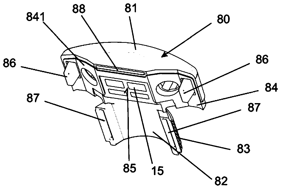
[0025] exist figure 1 A three-dimensional exploded representation of the cable lead-through 1 can be seen in the illustration of . The cable lead-through 1 serves to accommodate a prefabricated cable 2 , which is shown here, for example, as a cable section 3 and a plug 4 mounted thereon. Such a prefabricated cable 2 should pass through a recess 5 in the wall marked with reference 6 , only a section of which is shown here. The wall indicated at 6 can in particular be a wall of a switchgear cabinet which is not shown in its entirety. The cable lead-through 1 comprises two sub-elements 70 , 80 which are screwed together by means of two screws 9 . Each partial element 70 , 80 has a receiving section 71 , 81 facing the viewer and a threaded section 72 , 82 with an external thread 73 , 83 arranged facing away from the viewer. The threaded section 72 passes through the recess 5 of the wall 6 and is screwed through the nut 10 . Thus, the wall 6 is held clampingly between the nut 1...


PUM


Abstract

The invention relates to a cable bushing to be screwed to a wall having an opening for at least one prefabricated cable, said cable bushing comprising: - two partial elements which are screwed to oneanother in the mounted state, a threaded portion to be guided through the opening, said threaded portion having a screw thread and being formed by the two partial elements, each forming a part of itsperiphery, a receiving portion which adjoins the threaded portion in the axial direction of a rotational axis of said threaded portion, and which has, at least in parts, a larger outer diameter than the threaded portion, and which has at least one receiving opening for receiving at least one strain relief ferrule. The cable bushing according to the invention is characterised in that the division between the two partial elements is designed eccentrically such that the periphery of the receiving opening, extending about the at least one strain relief ferrule, in one of the partial elements is larger than that in the other partial element.

Description

technical field [0001] The invention relates to a cable lead-through for screwing with a wall having a recess for at least one cable. Background technique [0002] A cable lead-through of this type is known from DE 101 43 296 A1. The design of the cable lead-through there is suitable for accommodating so-called bundled conductors, ie conductors with already installed plugs or the like. For this purpose, the entire configuration of the cable lead-through can be divided centrally, so that the cables can be inserted into the cable lead-through in the separated state together with the cable sleeve which can be folded out and guided around the cable. Subsequently, the two halves of the cable lead-through are connected to each other, in particular clamped to each other. The cable entry with the prefabricated cable assembly can then pass through a sufficiently large opening, for example in the wall of the switch cabinet, so that the assembly can be screwed in the opening by means...

Claims


Application Information

Patent Timeline
IPC IPC(8): H02G3/08H02G3/22
CPCH02G3/083H02G3/088H02G3/22H02G15/007H02G3/0683H02G15/013
Inventor 布鲁诺·埃曼瓦伦丁·埃曼
Owner ICOTEK PROJEKT
Learn More