Composite material plate pre-compression clamping method

A composite material board and composite material technology, applied in the field of composite material board testing, can solve the problems of cumbersome assembly, difficult operation, large size, etc., and achieve the effect of compact and compact overall structure, simplified device structure, and promotion of influence rules

Inactive Publication Date: 2020-01-17
ZHEJIANG SCI-TECH UNIV
View PDF9 Cites 2 Cited by
  • Summary
  • Abstract
  • Description
  • Claims
  • Application Information

AI Technical Summary

Problems solved by technology

Currently, there is no standard test fixture setup for impact testing of composite panels under precompressive loads
However, the self-developed fixture device has many disadvantages such as huge size, cumbersome assembly and difficult operation.
However, for the drop weight impact test, the test space is closed and narrow, and it is difficult to place the pre-compression fixture

Method used


Image

  • Composite material plate pre-compression clamping method
  • Composite material plate pre-compression clamping method
  • Composite material plate pre-compression clamping method

Examples


Embodiment Construction

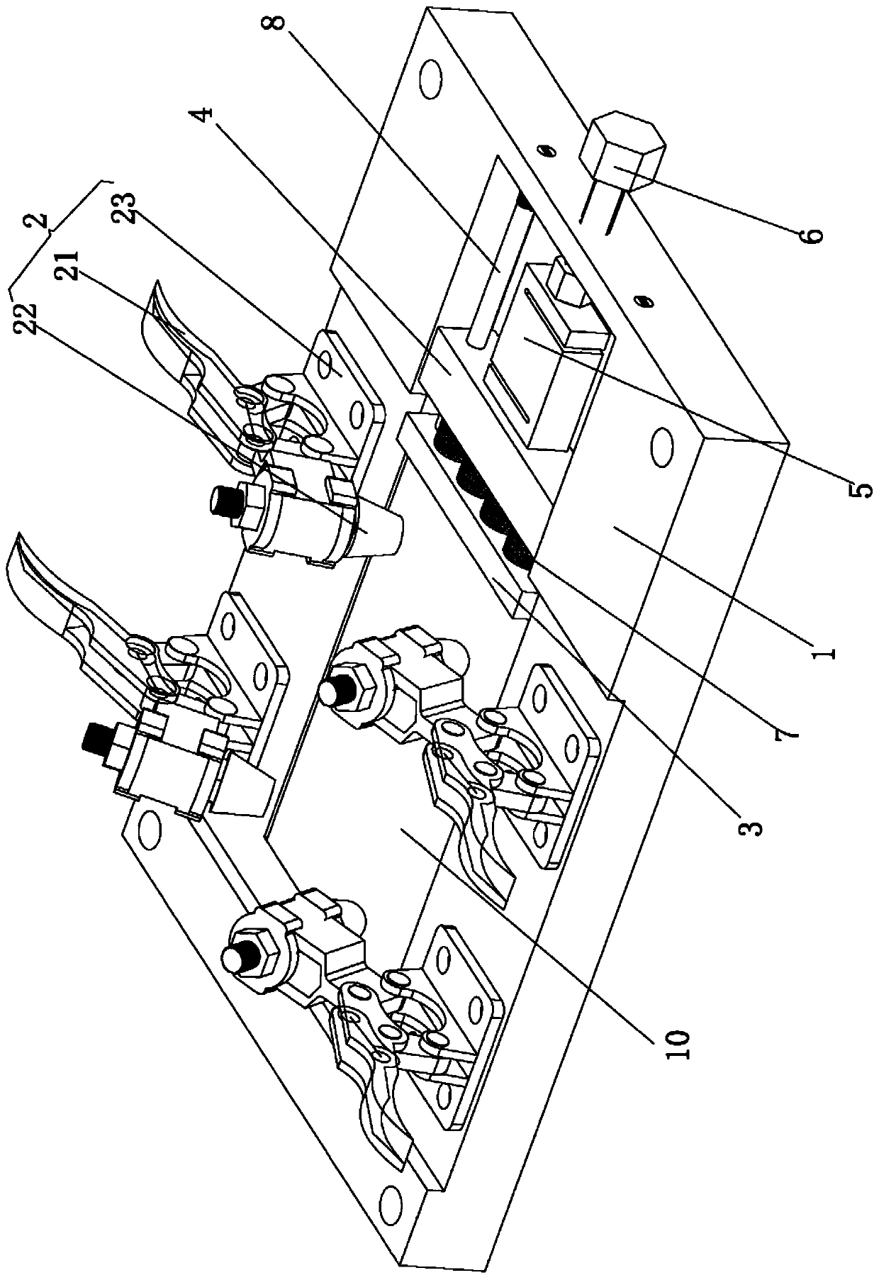
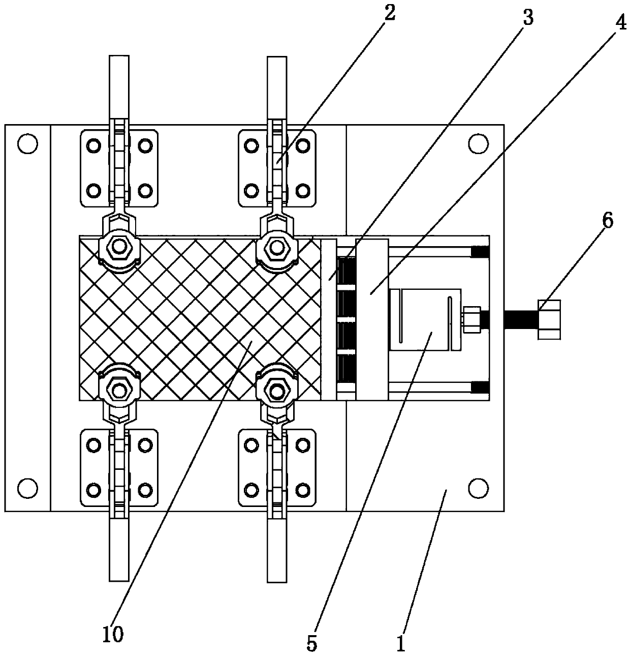
[0036] Please refer to the attached figure 1 to attach Figure 4 As shown, the present invention is a composite material plate pre-compression clamping device for compressing and clamping a composite material plate 10, which consists of a load plate 1, a horizontal clamp group 2, a compression block I3, a compression block II4, and a tension sensor 5 And several parts such as ejection bolt 6 are formed.

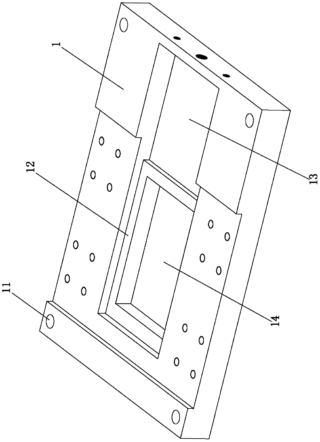
[0037] Wherein, four through holes 11 are provided at the corners of the four directions of the carrying board 1 , and the distances from the crossing lines of the edges are the same. Fixing bolts (not shown) are pierced through the through holes 11 to position the bearing plate 1 . A plate groove 12 is arranged on the carrying plate 1 ; a preload groove 13 is arranged on one side of the plate groove 12 . The preload groove 13 is located in the longitudinal direction of the composite material plate 10 and communicates with the plate groove 12 .

[0038] Further, the depth...


PUM


Abstract

The invention relates to a composite material plate pre-compression clamping method. The method comprises the following steps: placing a composite material plate: 1-1): rotating an ejection bolt; 1-2): floating a horizontal clamp group; 1-3): placing the composite material plate with the corresponding size into a plate groove; 1-4: sinking the horizontal clamp group, and enabling the tail end 1 ofthe horizontal clamp to be uniformly pressed on the upper surface of a composite material plate sample; 1-5: rotating the ejection bolt, and enabling a compression block I to apply quasi-static compression force to the axial direction of the composite material plate; 1-6: reading a feedback numerical value of the tension sensor, and stopping rotating the ejection bolt after a specified pre-compression acting force numerical value is reached; taking out the composite material plate: 2-1): rotating the ejection bolt; 2-2): floating the horizontal clamp group, and enabling the tail end of the horizontal clamp to be away from the horizontal plane; and 2-3: taking out the composite material plate sample with the corresponding size. The method is convenient to operate and reusable, and has a promotion effect on researching the influence rule of the pre-compression acting force on the impact response of the composite material plate.

Description

【Technical field】 [0001] The invention relates to a test method for a composite material plate, in particular to a pre-compression clamping method for a composite material plate, and belongs to the technical field of test methods for mechanical properties of composite materials. 【Background technique】 [0002] The large demand for lightweight structural parts in modern aerospace, automobile, high-speed train and other industrial fields has promoted the development and application of composite material plates. Before using the composite sheet, its mechanical properties are the main test indicators. Among them, the impact performance under quasi-static compressive load is an important mechanical performance index of composite sheet, which reflects the ability of the material to maintain structural integrity under complex service environments. [0003] Unlike impact testing of composite panels under free load, drop weight impact testing under precompressive loads requires the ...

Claims


Application Information

Patent Timeline
Patent Type & Authority Applications(China)
IPC IPC(8): G01N3/04G01N3/303G01N3/14
CPCG01N3/04G01N3/303G01N3/14G01N2203/0026G01N2203/0033G01N2203/0035G01N2203/0282G01N2203/0423
Inventor 潘忠祥王臻宇应志平吴震宇胡旭东
Owner ZHEJIANG SCI-TECH UNIV
Why Eureka
Try Eureka