
Manipulation display panel, manufacture method thereof and induction cooker

A display panel and induction cooker technology, which is applied in the field of induction cooker, can solve the problems of touch feedback sensitivity reduction, touch operation interference, and inability to ensure surface bonding, etc., and achieve the effect of improving touch sensitivity

Pending Publication Date: 2020-01-17
BEIJING SMARTMI TECH
View PDF0 Cites 0 Cited by
  • Summary
  • Abstract
  • Description
  • Claims
  • Application Information

AI Technical Summary

Problems solved by technology

In the prior art, the character display film is an integral film, that is, when pasting, the entire film is pasted on the surface of the control display module; in this way, when the touch spring is used in the control display module, due to the touch spring The top of the control display module is higher than the surface of the control display module. Therefore, it is impossible to ensure that the character display film is completely attached to the surface of the control display module after pasting. There is a gap between the character display film near the touch spring and the surface of the control display module. , the gap will interfere with the touch operation to a certain extent, resulting in a decrease in touch feedback sensitivity

Method used


Image

  • Manipulation display panel, manufacture method thereof and induction cooker
  • Manipulation display panel, manufacture method thereof and induction cooker
  • Manipulation display panel, manufacture method thereof and induction cooker

Examples


Embodiment Construction

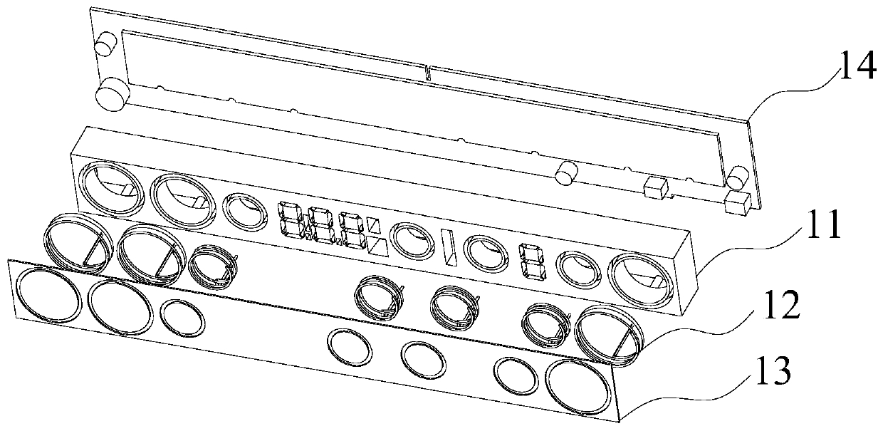
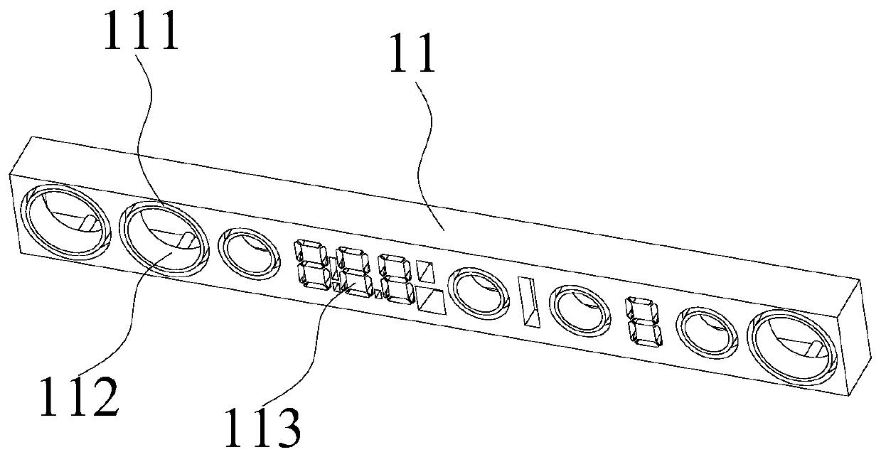
[0025] refer to figure 1 A schematic structural diagram of the manipulation display panel provided in this embodiment is shown; figure 2 An exploded view of the manipulation display panel provided in this embodiment is shown; image 3 A schematic structural diagram of the manipulation display module provided in this embodiment is shown; Figure 4 A schematic structural view of the character display film provided in this embodiment is shown.

[0026] like Figure 1-4 As shown, the present embodiment provides a control display panel, which includes a control display module 11. The surface of the control display module 11 is provided with an annular groove 111. The foot is perforated, and the touch spring 12 is arranged in the annular groove 111. The top of the touch spring 12 is higher than the surface of the control display module 11, and the solder leg of the touch spring 12 is connected to the circuit board 14 through the solder leg perforation; the control display panel ...


PUM


Abstract

The invention relates to the technical field of induction cookers, in particular to a manipulation display panel, a manufacture method thereof and an induction cooker. The manipulation display panel comprises a manipulation display module, wherein an annular groove is formed in the surface of the manipulation display module, a welding foot passing hole which runs through the bottom surface of themanipulation display module is formed in the bottom of the annular groove, a touch control spring is arranged in the annular groove, the top end of the touch control spring is higher than the surfaceof the manipulation display module, and a welding foot of the touch control spring passes through the welding foot passing hole, and is connected with a circuit board. The manipulation display panel further comprises a character display film, wherein an annular hole is formed in the character display film, the character display film is attached to the surface of the manipulation display module, and the top end of the touch control spring passes through the annular hole. According to the manipulation display panel, the touch control spring passes through the character display film through the annular hole, and the character display film and the manipulation display module are attached to each other in a seamless mode. When a person performs touch manipulation, hands of the person directly touch the touch control spring, no interference factor exists, and improvement of touch control sensitivity is facilitated.

Description

technical field [0001] The invention relates to the technical field of electromagnetic ovens, in particular to a control display panel, a manufacturing method thereof, and an electromagnetic oven. Background technique [0002] The control display panel has control functions and display functions, including switches, function selection buttons, digital tubes, display screens, and the like. At present, commonly used control display panels include a control display module, and switches, function selection buttons, digital tubes, display screens, etc. are collectively arranged on the control display module. [0003] In order to distinguish the functional components on the control display module, a layer of character display film is pasted on its surface. In the prior art, the character display film is an integral film, that is, when pasting, the entire film is pasted on the surface of the control display module; in this way, when the touch spring is used in the control display ...

Claims


Application Information

Patent Timeline
Patent Type & Authority Applications(China)
IPC IPC(8): F24C7/08
CPCF24C7/081
Inventor 刘铁苏峻姚亮亮黄亮余久平梁万春陈栋袁子明王梦囡
Owner BEIJING SMARTMI TECH
Learn More