Animal-drawn power generation device
A power generation device and animal power technology, applied in the direction of electromechanical devices, transmission devices, electrical components, etc., can solve the problems of less application of animal power generation, high cost of conventional power generation equipment, low power generation efficiency, etc., and achieve low cost, low maintenance cost, and improved functional effect
- Summary
- Abstract
- Description
- Claims
- Application Information
AI Technical Summary
Problems solved by technology
Method used
Image
Examples
Embodiment 1
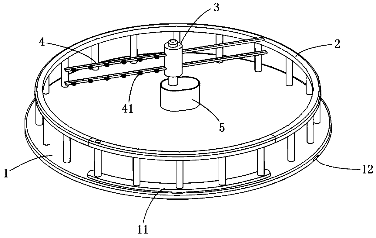
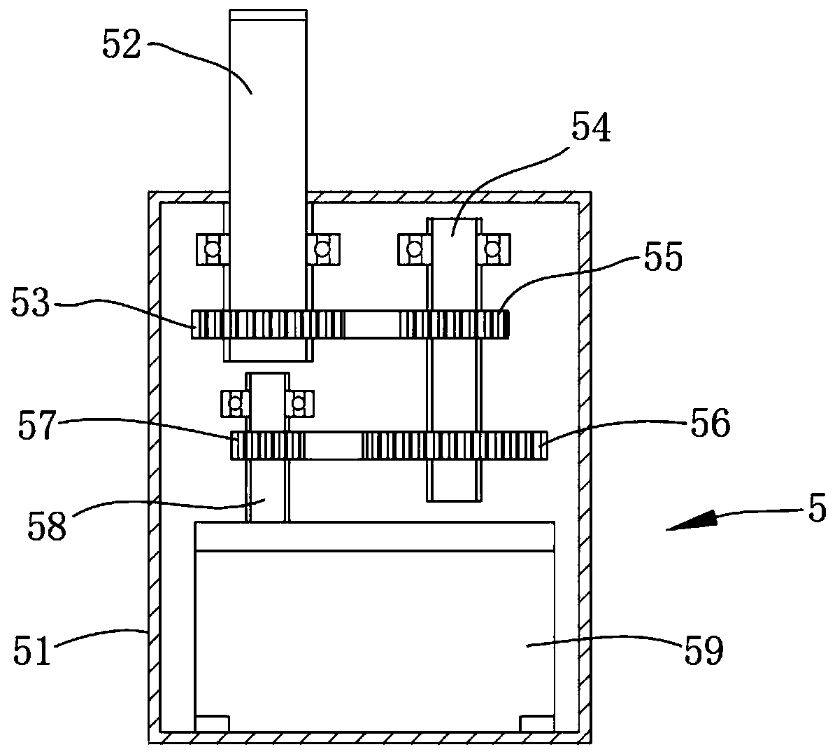
[0036] Such as figure 1 As shown, the embodiment of the present invention provides an animal power generating device, which includes a bottom plate body 1 and a power generation device 5 fixed at the center of the top surface of the bottom plate body 1, and the input end of the power generation device 5 is fixedly connected with two sets of opposing arrangements. The pull arm 4 is used to pull the pull arm 4 to rotate by using domesticated cattle, donkeys, horses and other large livestock, so as to drive the power generation equipment 5 to work to realize animal power generation, which has low cost and high profit. Compared with other energy investments Low maintenance cost, low unit cost, low probability of being affected by environmental factors, weather and climate, and geographical location, and strong advantages of sustainable development and controllable development. The specific settings are as follows:
[0037] The outer edge of the top end surface of the bottom plate...
Embodiment 2
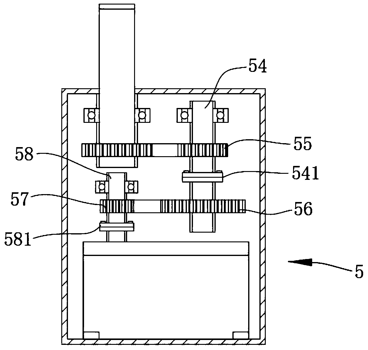
[0042] In embodiment 2, for the same structure as in embodiment 1, give the same symbol, omit the same description, embodiment 2 has made improvement on the basis of embodiment 1, as image 3 As shown, the sprocket positioning shaft 54 is provided with a speed regulating flange 1 54 between the first transmission sprocket 55 and the second transmission sprocket 56, and the generator input shaft 58 is provided with a speed regulating flange 1 located between the output sprocket 57 and the speed-regulating flange 2 581 between the generator module 59, which can be used to arbitrarily replace the second drive sprocket 56 with different graduation circles on the sprocket positioning shaft 54 and the different graduations on the generator input shaft 58 according to requirements The circular output sprocket 57 can be flexibly configured and adjusted according to livestock of different types and sizes, which improves the functionality and practicability of the device.
Embodiment 3
[0044] In embodiment 3, for the same structure as in embodiment 1, the same symbol is given, and the same description is omitted. Embodiment 3 is improved on the basis of embodiment 1, as Figure 4 As shown, several reinforcement rods 42 are provided on each group of said pulling arms 4, and auxiliary push arms 6 are respectively affixed on said reinforcement rods 42, in order to play a role on the back of the livestock through the auxiliary push arms 6. It must be counteracting.
[0045] Specifically, such as Figure 5 As shown, the auxiliary push arm 6 includes a push arm positioning rod 61, an adaptive rod 62, a push arm spring 63, an inertia push body 64, a steel ball 65 and a widening plate 66, and one end of the push arm positioning rod 61 is fixed Connected to the reinforcing rod 42, the other end of the push arm positioning rod 61 is provided with a limiting block 611, and the inside of the self-adaptive rod 62 is provided with a sliding cavity 621, and the limiting b...
PUM
| Property | Measurement | Unit |
|---|---|---|
| Length | aaaaa | aaaaa |
Abstract
Description
Claims
Application Information
 - Generate Ideas
- Intellectual Property
- Life Sciences
- Materials
- Tech Scout
- Unparalleled Data Quality
- Higher Quality Content
- 60% Fewer Hallucinations
Browse by: Latest US Patents, China's latest patents, Technical Efficacy Thesaurus, Application Domain, Technology Topic, Popular Technical Reports.
© 2025 PatSnap. All rights reserved.Legal|Privacy policy|Modern Slavery Act Transparency Statement|Sitemap|About US| Contact US: help@patsnap.com


